

Pressing plate structure fixed on clamping groove and use method thereof
A technology of clamping groove and pressing plate, applied in the field of pressing plate structure, can solve the problems of inaccurate pressing and positioning, complex structure, etc., and achieve the effect of simple structure, simple principle and accurate positioning
- Summary
- Abstract
- Description
- Claims
- Application Information
AI Technical Summary
Problems solved by technology
Method used
Image

Examples
Embodiment
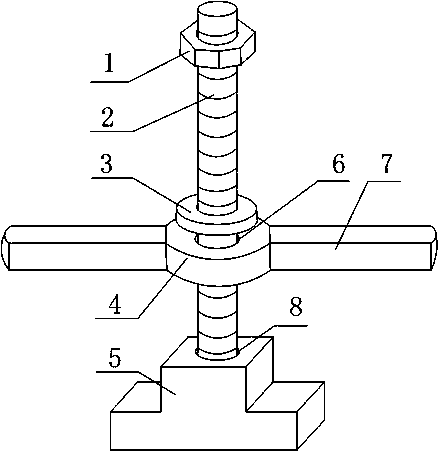
[0016] Such as figure 1 As shown, the structure of the pressing plate fixed on the card slot includes a fixed block 5, and the fixed block 5 is provided with a threaded through hole 8, and the threaded through hole 8 is internally screwed with a screw rod 2, and the outer wall of the screw rod 2 is fitted There is a nut 1, a positioning device is arranged between the nut 1 and the fixing block 5, a through hole 6 is arranged on the positioning device, and the screw rod 2 passes through the inside of the through hole 6. Through the screw thread on the screw rod 2, the operator can screw the nut 1 to fix the positioning device, and adjust according to the length of the workpiece, so that workpieces of different sizes can be fixed, and the fixing effect is good.
[0017] A washer 3 is arranged between the nut 1 and the positioning device, and the washer 3 fits on the outer wall of the screw rod 2 . The washer 3 is used as a buffer component between the nut 1 and the positioning ...
PUM
 Abstract
Description
Claims
Application Information