Quantitative material injection device of mould

A technology of feeding device and mold, applied in the direction of feeding device, manufacturing tool, etc., can solve the problems of uneven injection, high labor intensity, hidden safety hazards, etc., and achieve reasonable structure design, convenient feeding flow, and stable equipment operation. Effect

Active Publication Date: 2014-12-24
东莞市宜曼洲电子科技有限公司
View PDF6 Cites 15 Cited by
  • Summary
  • Abstract
  • Description
  • Claims
  • Application Information

AI Technical Summary

Problems solved by technology

[0002] Traditional mold injection usually adopts two methods, one is to inject the material when the mold is in the mold closing state, and the other is to inject the material into the cavity through manual injection. The former needs to be injected under a certain pressure condition. The raw material is injected into the feed port and the main runner, and then enters each cavity of the mold through the sub-runner. The mold structure is complicated, the production is difficult, the production cost is high, and the injection is uneven. The latter injects the raw material into the fixed mold. In the cavity of the mold, and then use a scraper to scrape off the excess raw materials outside the cavity, the purpose of quantitative injection has been achieved, the production efficiency is low, the labor intensity is high, and there are certain safety hazards; and dry powder molding is a A more advanced molding process, and began to replace traditional products such as spark plugs, ceramic balls, plungers, vacuum shells and other products produced by ceramics with advantages. In the dry powder molding process, the dry powder is compressed in a specific mold. Traditional The mold injection method can no longer meet the needs of production and processing, and cannot be matched with the existing isostatic pressing molding equipment

Method used


Image

  • Quantitative material injection device of mould
  • Quantitative material injection device of mould
  • Quantitative material injection device of mould

Examples


Embodiment

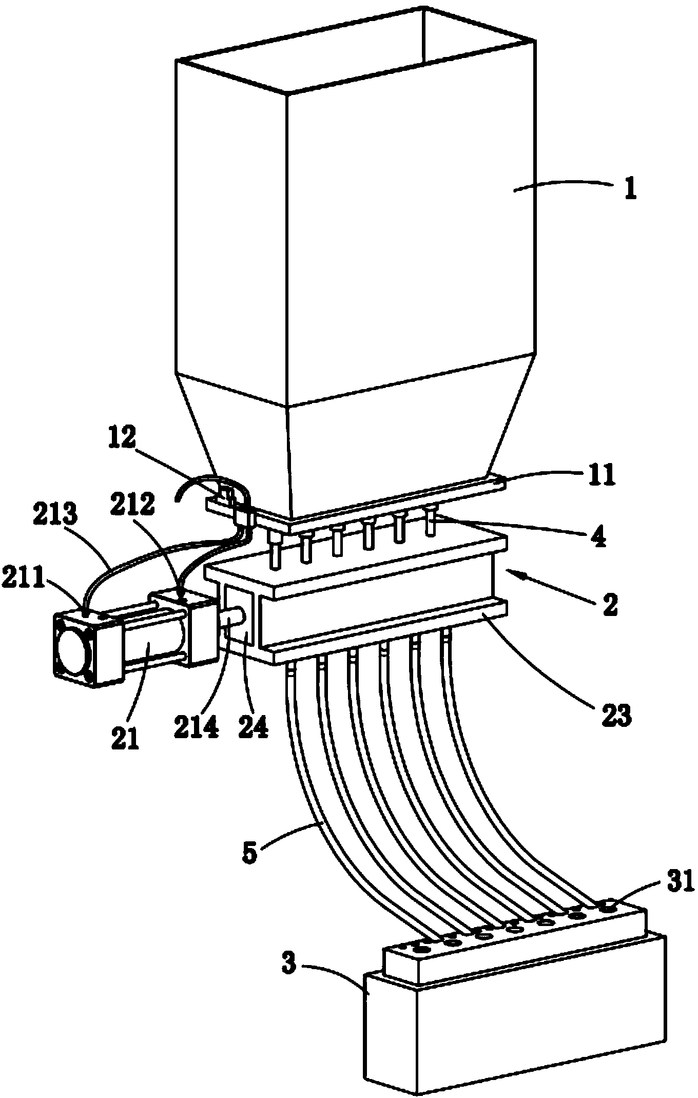
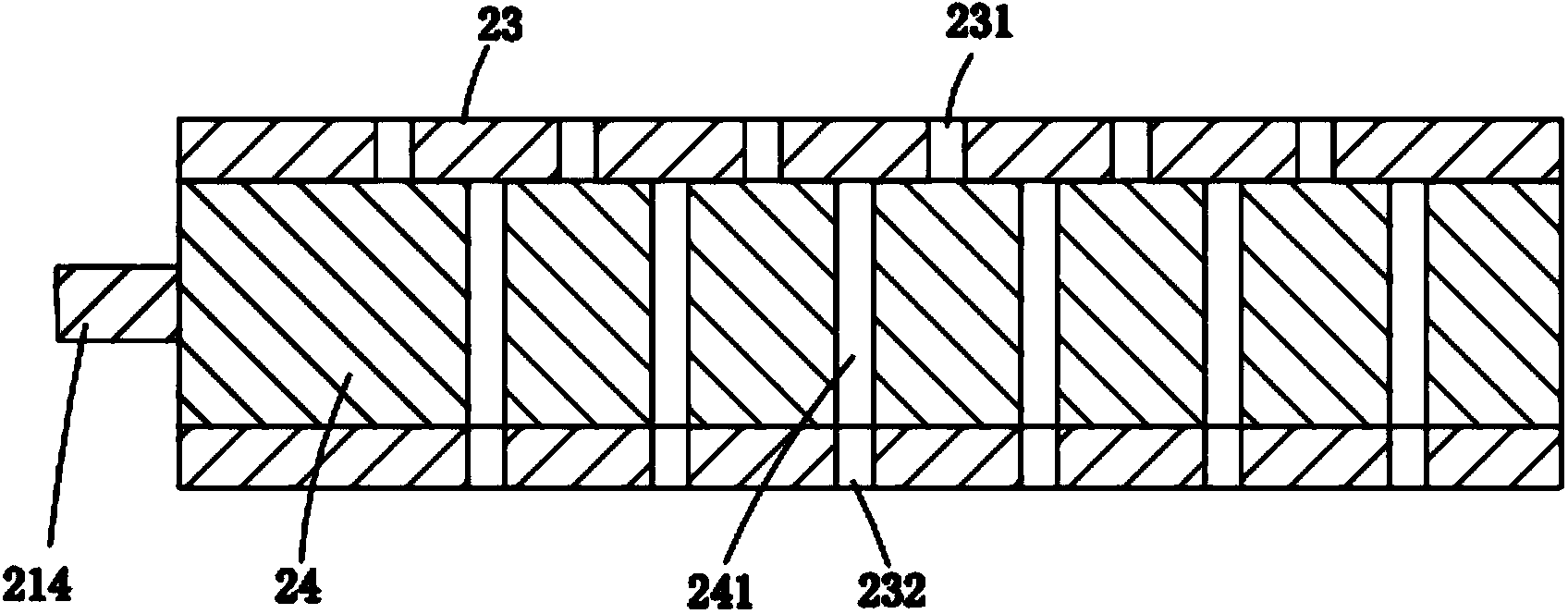
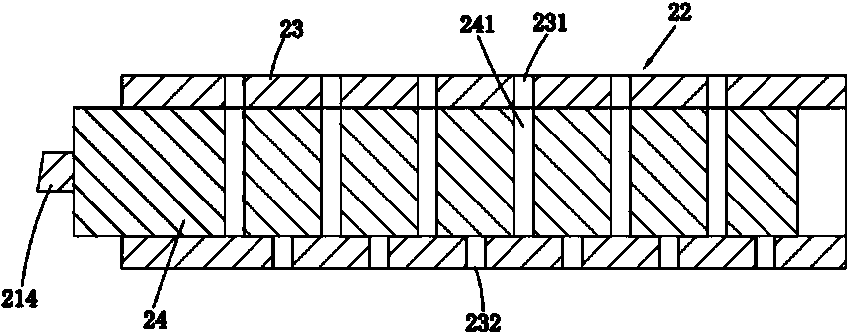
[0020] Such as figure 1 As shown, a mold quantitative injection device includes a hopper 1 with an open upper end, a feeding device 2 and a lower mold body 3, the bottom of the hopper 1 is provided with a sealing plate 11, and several outlets are evenly distributed on the sealing plate 11. Each outlet is provided with a feed pipe 4; the feeding device 2 includes a cylinder 21 and a material injection mechanism 22, and an air inlet 211 and an air outlet 212 are also provided above the cylinder 21, and the air inlet 211 and the air outlet 212 Connected to the external air source through the connecting pipe 213; the injection mechanism 22 is driven by the cylinder 21 and placed directly below the hopper 1; as figure 2 with image 3 As shown, the injection mechanism 22 includes a housing 23 and a slider 24 that is slidable in the housing 23. The length of the slider 24 is equal to the inner cavity of the housing 23, and its upper and lower surfaces are respectively connected to ...


PUM


Abstract

The invention relates to a quantitative material injection device of a mould. The quantitative material injection device comprises a hopper, a feeding device and a lower mould body, wherein the hopper is further provided with a material level detection sensor connected with a main controller and an opening sealing plate is arranged at the bottom of the hopper; a plurality of outlets are uniformly formed in the opening sealing plate; each outlet is provided with a material guide pipe; the feeding device comprises an air cylinder and a material injection mechanism; a plurality of material injection openings corresponding to the outlets of the opening sealing plate are formed in the upper surface of the material injection mechanism; a plurality of discharging holes are formed in the lower surface of the material injection mechanism; a plurality of cavities are vertically formed in the lower mould body; the front side of each cavity is obliquely provided with a material injection pipe communicated with the cavity; the tops of the material injection pipes are correspondingly connected with the discharging holes respectively. The quantitative material injection device can be used for rapidly feeding back the volume of raw materials in the hopper in time through the material level detection sensor so that a certain pressure value is maintained in the hopper; the feeding device is driven by the air cylinder to automatically and quantitatively feed and discharge the materials at intervals, and furthermore, the feeding amount in the mould is controlled; the quantitative material injection device is reasonable in structure and high in production efficiency and can be used for continuously and smoothly discharging the materials.

Description

Technical field: [0001] The invention relates to a material injection device, in particular to a mold quantitative injection device. Background technique: [0002] Traditional mold injection usually adopts two methods, one is to inject the material when the mold is in the mold closing state, and the other is to inject the material into the cavity through manual injection. The former needs to be injected under a certain pressure condition. The raw material is injected into the feed port and the main runner, and then enters each cavity of the mold through the sub-runner. The mold structure is complicated, the production is difficult, the production cost is high, and the injection is uneven. The latter injects the raw material into the fixed mold. In the cavity of the mold, and then use a scraper to scrape off the excess raw materials outside the cavity, the purpose of quantitative injection has been achieved, the production efficiency is low, the labor intensity is high, and t...

Claims


Application Information

Patent Timeline
Patent Type & Authority Applications(China)
IPC IPC(8): B28B13/02
CPCB28B13/0215
Inventor 董宝亮
Owner 东莞市宜曼洲电子科技有限公司
Why Eureka
Try Eureka