A tire for a heavy load

A heavy-duty, tire technology, applied in tire parts, treads, transportation and packaging, etc., can solve the problems of tire shape change, rubber collapse, permanent deformation, etc. collapse effect

Inactive Publication Date: 2014-12-24
SUMITOMO RUBBER IND LTD
View PDF7 Cites 7 Cited by
  • Summary
  • Abstract
  • Description
  • Claims
  • Application Information

AI Technical Summary

Problems solved by technology

With the displacement of the bead core d, the rubbing rubber c is compressed between the bead core d and the rim r, so there is a problem that the rubber collapses (depressi

Method used


Image

  • A tire for a heavy load
  • A tire for a heavy load
  • A tire for a heavy load

Examples


Embodiment

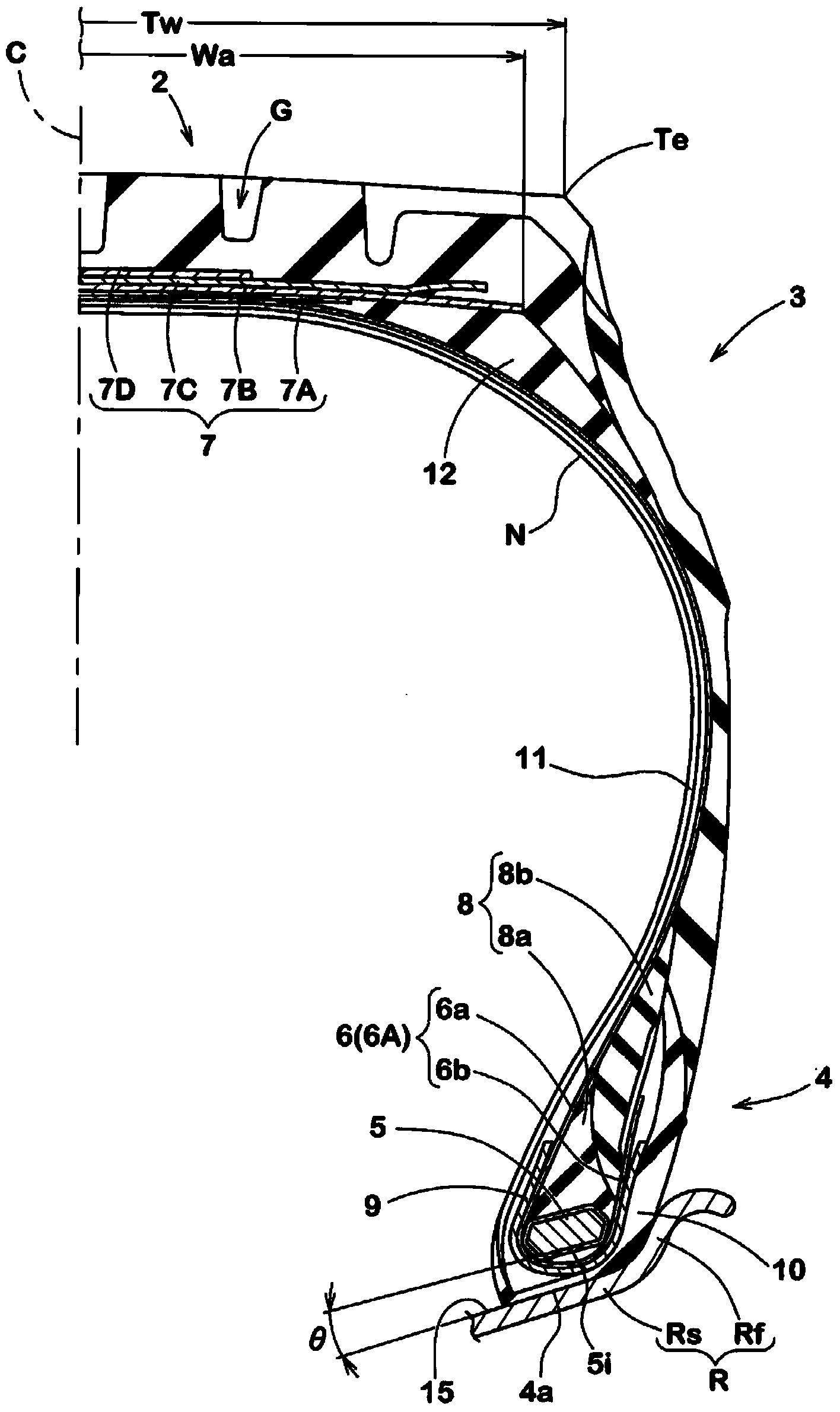
[0057] Based on the specifications in Table 1, a trial production with figure 1 The shown basic structure is a heavy-duty tire with a size of 11R22.5, and the degradation performance and durability performance of each test tire were tested. Common specifications and test methods for each test tire are as follows.

[0058] The wire diameter Da of the filament of the steel cord of the bead reinforcement layer: 0.1 mm

[0059] The angle of the carcass cord relative to the tire equator: 90 degrees

[0060]

[0061] Each test tire was placed in a thermostat at 70° C. for 10 days under the following internal pressure conditions to accelerate its deterioration. Next, the degraded tires were run on a roller tester under the following conditions. Thereafter, the amount of displacement of the bead heel point due to rubber collapse before and after running was measured. The results are represented by a 5-point scale in which the value of Comparative Example 1 was converted to 1 an...


PUM


Abstract

A tire for a heavy load of the invention raises the durability of a tire bead portion. The tire for the heavy load comprises a tire beam core (5), a tire body (6), a tire bead filler (8), a tire bead reinforcement layer (9) and anti-rubbing rubber (10). The tire bead reinforcement layer (9) is provided with steel cords (9C) which are arranged at angles of 40-70 degrees relative to the circumferential direction of the tire. In a normal state, the ratio (B/A) of a maximum thickness (B) of a orthogonal portion between the tire bead core (5) and the inner side surface (5i) to a maximum width (A) of a parallel portion between the tire bead core (50 and the inner side surface (5i) is 0.3-0.5. In a condition that a normal load is loaded in a normal state and a normal load is grounded at an outer inclination angle of 0 degree, an angle between the inner side surface of the tire bead core (5) and a rim seat surface (15) of a normal rim (R) is 0 degree to +-3 degrees. The ratio (D/A) of the shortest distance (D) between tire axial outer end of the tire bead core (5) and the outer surface of the anti-rubbing rubber (10) to the largest width (A) of the tire bead core (5) is 0.4-0.8.

Description

technical field [0001] The present invention relates to a heavy-duty tire with improved durability of bead portions. Background technique [0002] like Figure 5 As shown, there is known a heavy duty tire a provided with a carcass e and a rubbing rubber c, wherein the carcass e is composed of a carcass ply having: The tread part t reaches the main body part e1 of the bead core d of the bead part b through the sidewall part s, and the turning part e2 which is connected to the main body part e1 and turns back around the bead core d from the inner side to the outer side in the tire axial direction; The anti-scratch rubber c is arranged on the outer side in the tire axial direction of the outer end of the bead core d in the tire axial direction. [0003] Since such a heavy duty tire a is loaded with a high internal pressure, a tensile force f that pulls the main body portion e1 of the carcass ply outward in the tire radial direction acts. As a result, the bead core d displaces...

Claims


Application Information

Patent Timeline
IPC IPC(8): B60C15/04B60C15/06
CPCB60C15/0607B60C2200/06
Inventor 丸冈清人
Owner SUMITOMO RUBBER IND LTD
Why Eureka
Try Eureka