
Fluorescent observation device with spaced covers, base frame and fluorescence microscope

An observation device and microscope technology, applied in microscopes, optics, telescopes, etc., can solve problems such as a large increase in residual germs, damage to observation devices, and germ infection.

Inactive Publication Date: 2014-12-24
LUMOS TECH
View PDF5 Cites 3 Cited by
  • Summary
  • Abstract
  • Description
  • Claims
  • Application Information

AI Technical Summary

Problems solved by technology

In other words, the larger the range of activity of the fluorescent object to be observed, the wider the distribution of pollution, and the harder the cleaning work, which greatly increases the possibility of residual germs
In short, if the range of activities is too large, it will not only hinder the experimental observation; the activities of eating, biting, licking and gnawing may cause damage to the observation equipment; it will also cause hygienic troubles and easily cause a hotbed of germ infection
[0005] On the other hand, for example, general animal centers are responsible for providing various experimental animals to various laboratories, or taking care of experimental animals on their behalf. When each laboratory comes to pick up their own experimental animals, how to confirm that the above-mentioned fluorescent animals are indeed fluorescent? There is no simple and effective device for detection, and it is easy to cause controversy. Even if irradiated with ultraviolet light, when most experimental fluorescent mice are grouped together, even if one or two of them have no fluorescent reaction, it is not easy to distinguish from them. It is still necessary to grasp and distinguish them one by one. Each fluorescent reaction; therefore, a simple and easy-to-clean detection device is needed
[0006] From the situation described above, it can be known that the previous observation devices could not improve the observation efficiency, nor could it improve the sanitary environment of the observation and reduce the clean-up burden of the experimenters

Method used


Image

  • Fluorescent observation device with spaced covers, base frame and fluorescence microscope
  • Fluorescent observation device with spaced covers, base frame and fluorescence microscope
  • Fluorescent observation device with spaced covers, base frame and fluorescence microscope

Examples


Embodiment Construction

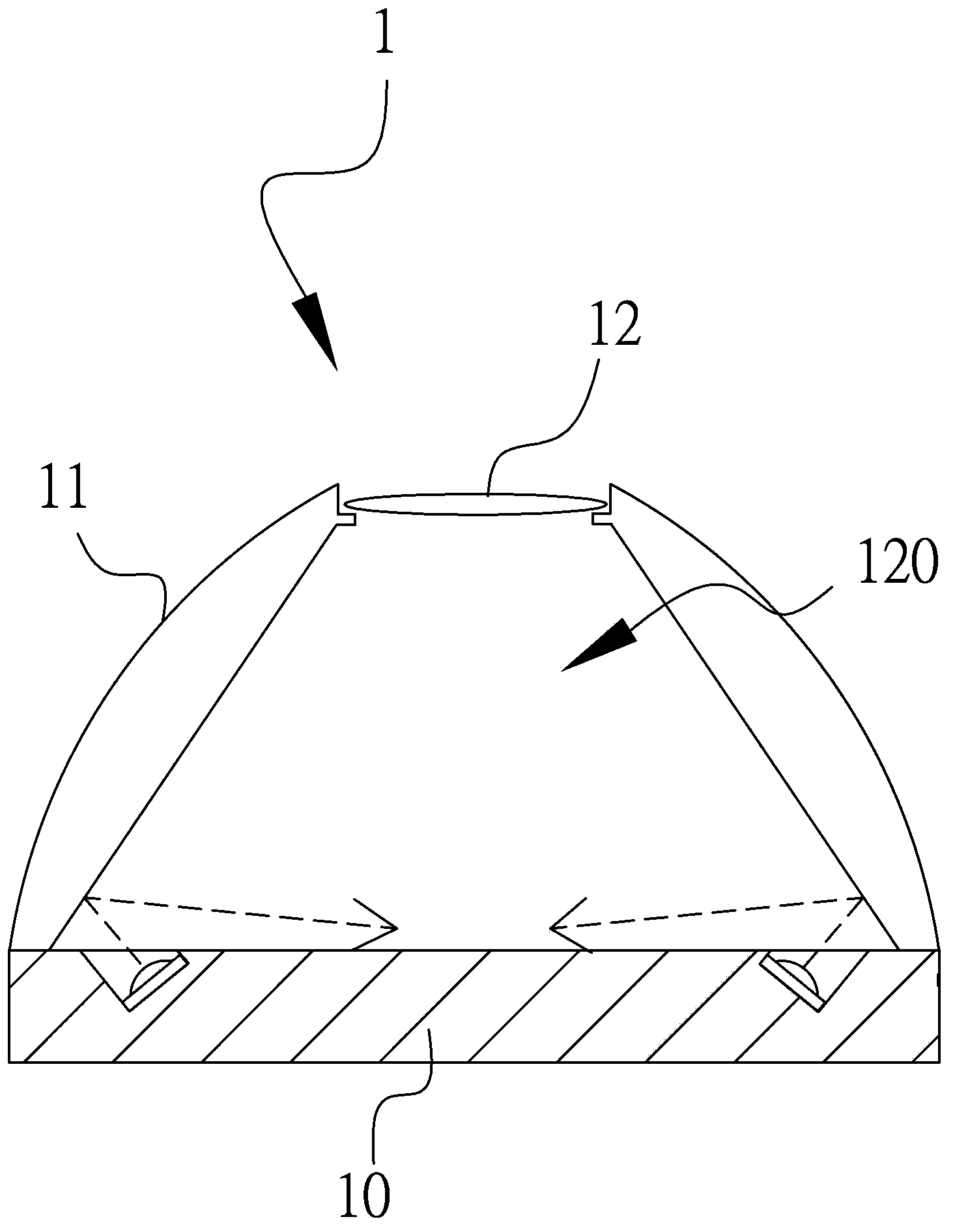
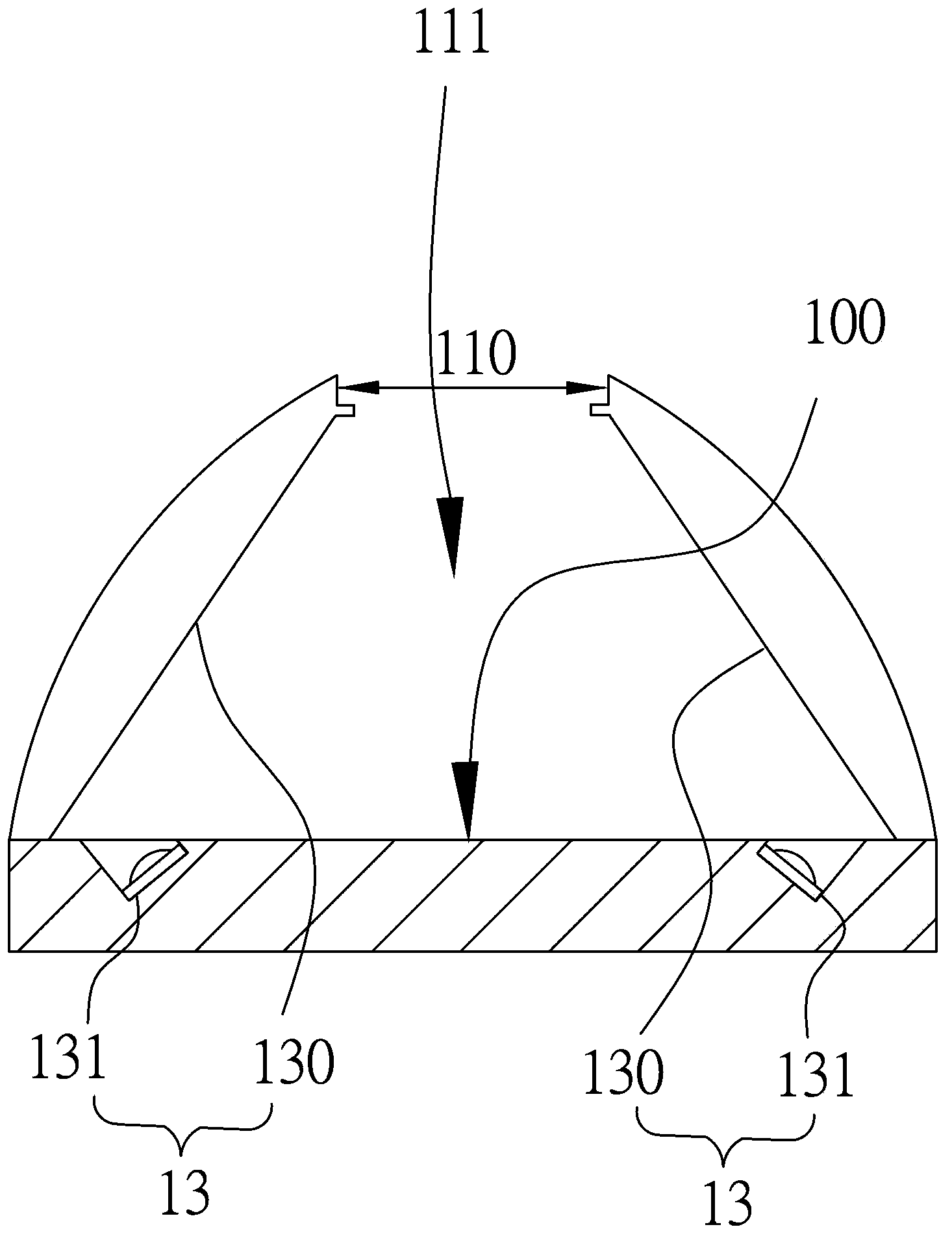
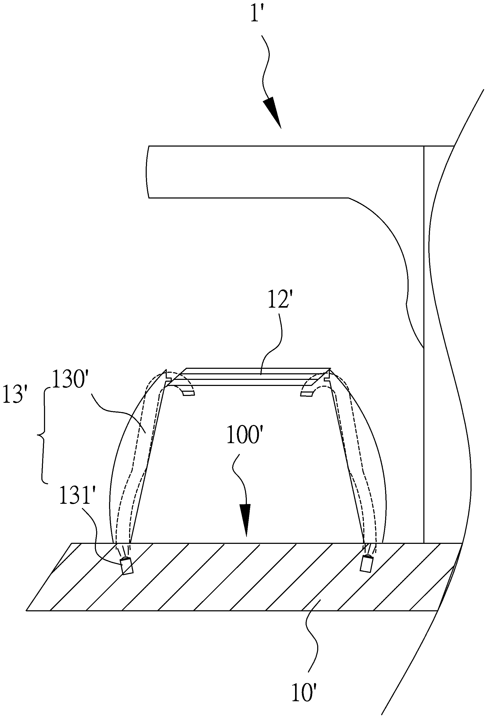
[0032] The first preferred embodiment of the present invention is a fluorescence observation device 1 with a spaced mask, for reference figure 1 and figure 2 As shown, it includes a base 10, a predetermined observation position 100 for observing the fluorescent object to be observed is formed on the base 10, and the active area of ​​the fluorescent object to be observed is preset on the base 10; and then by a mask 11, A light-shielding chamber 111 is surrounded on the base 10 to block external light sources from interfering with experimental observation and to limit the range of activity of fluorescent objects to be observed. The light-shielding chamber 111 is not completely closed, but still exposes a light-transmitting viewing hole 110 for easy observation. In order to prevent the fluorescent object to be observed from contacting the objective lens through the light-transmitting hole 110, or passing through the light-transmitting hole 110 from the light-shielding chamber 1...


PUM


Abstract

A fluorescent observation device with spaced covers can limit the movement range of a fluorescent article to be observed, so that the fluorescent article to be observed can be conveniently observed by means of the fluorescent observation device. The fluorescent observation device comprises bases with preset observation positions, the covers, light-pervious shelters and light source assemblies, wherein the covers are correspondingly connected with the bases, cover the bases correspondingly, define light shielding cavities with the bases in an enclosed mode and form light-pervious observation holes; the light-pervious shelters cover the light-pervious observation holes and define a blocking spaces with the bases and the covers in an enclosed mode; each light source assembly comprises a light source which can excite light at a low angle in the direction of the corresponding preset observation position.

Description

【Technical field】 [0001] The invention relates to a fluorescence observation device, a base frame and a fluorescence microscope with spaced masks for fluorescence observation. 【Background technique】 [0002] Fluorescence technology is often used in the analysis and tracking of cells in biological research. An important research in the field of biological science is gene transplantation. For the convenience of observation, the implanted gene will often produce fluorescent protein to observe the fluorescent reaction of the object to be observed. , the success or failure of gene implantation can be confirmed, and the organisms with successful transplantation can be further studied in depth. Among them, the requirements of the experiment for the fluorescent objects to be observed generally tend to have a large number of reproduction and a short reproduction cycle, can quickly accumulate a large number of offspring, and have characteristics similar to human beings. Species that ...

Claims


Application Information

Patent Timeline
IPC IPC(8): G02B23/16G02B23/00G02B21/00
Inventor 杨之逸
Owner LUMOS TECH
Learn More