Method for solving camera homography matrix and projector homography matrix

A homography matrix and projector technology, applied in the field of computer vision, can solve problems affecting calibration accuracy and robustness, calibration accuracy dependence, etc., and achieve the effect of simple method, high precision, and strong robustness

Inactive Publication Date: 2014-12-24
CHANGCHUN UNIV OF SCI & TECH
View PDF5 Cites 16 Cited by
  • Summary
  • Abstract
  • Description
  • Claims
  • Application Information

AI Technical Summary

Problems solved by technology

The calibration method based on phase technology requires multiple projections of sinusoidal gratings, and the calibration accuracy depends on the accuracy of absolute phase unwrapping; the calibration method based on cross-ratio invariance requires straight line fitting and gray-scale interpolation, and the object to be measured cannot be directly calculated from the calibration results The real size of the camera; the calibration method of the projector based on the calibration camera is widely used, and a specially designed calibration board is required. The design of the calibration board affects the calibration accuracy and robustness

Method used


Image

  • Method for solving camera homography matrix and projector homography matrix
  • Method for solving camera homography matrix and projector homography matrix
  • Method for solving camera homography matrix and projector homography matrix

Examples


Embodiment Construction

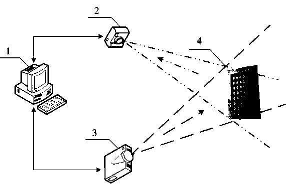
[0032] Below in conjunction with accompanying drawing, the present invention will be further described: as figure 1 Shown, a kind of solution method of camera homography matrix and projector homography matrix, computer 1, video camera 2, projector 3, calibration board 4; It is characterized in that: camera 2 and projector 3 are connected with computer by cable 1 connection, follow the steps below:

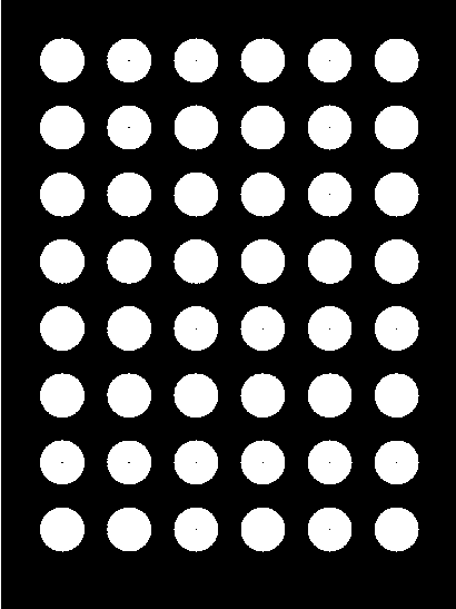
[0033] Step 1, in computer 1, generate a camera calibration image, such as figure 2 As shown, the RGB values ​​of the background color of the camera calibration image are 100, 100, and 100 respectively; the camera calibration image includes 48 white circles with the same radius and a radius of 9mm, arranged in 8 rows and 6 columns, between the centers of two adjacent circles The distance is 23.5mm. Use A4 paper to print out the calibration image of the camera, and paste it on a flat board to form the calibration board 4 .

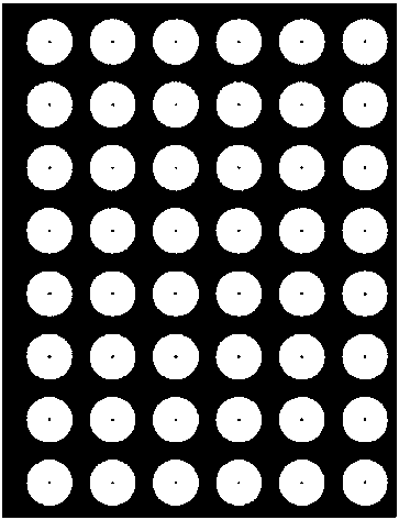
[0034] Step 2, in computer 1, generate a projector cal...


PUM


Abstract

The invention relates to a method for solving a camera homography matrix and a projector homography matrix. The method for solving the camera homography matrix and the projector homography matrix is characterized in that a camera and a projector are both connected with a computer through cables, and the method comprises the following steps that in the computer, a camera calibration image is generated, in the computer, a projector calibration image is generated, and the camera calibration image and the projector calibration image are stored in the computer; the camera and the projector are fixedly placed on the front portion of a calibration plate, and it is guaranteed that the calibration plate is placed within the view field range of the camera and the projector; the calibration plate is taken through the camera, and a camera calibration plate image is obtained; the calibration plate is kept not be moved, the projector calibration image is all projected to the calibration plate through the projector, the camera is used for shooting the calibration plate, and a projector calibration plate image is obtained. According to the method for solving the camera homography matrix and the projector homography matrix, the camera and the projector can be quickly calibrated, and therefore the camera homography matrix and the projector homography matrix can be obtained.

Description

technical field [0001] The invention relates to a method for solving a camera homography matrix and a projector homography matrix, and belongs to the technical field of computer vision. Background technique [0002] The structured light measurement method is one of the most promising and widely used three-dimensional measurement methods, which has the advantages of non-contact, high precision and fast speed. The structured light measurement method can adopt binocular stereo vision technology or monocular stereo vision technology. Monocular vision technology is widely used because of its simple structure, no need to consider camera synchronization issues, small amount of processed data, and high efficiency of point cloud reconstruction. It can be seen from the following formula, [0003] [0004] [0005] In order to determine the corresponding relationship between the camera image coordinate system and the projector optical coordinate system and the world coordinate s...

Claims


Application Information

Patent Timeline
Patent Type & Authority Applications(China)
IPC IPC(8): G06T7/00
Inventor 张超杨华民韩成权巍蒋振刚冯欣范静涛
Owner CHANGCHUN UNIV OF SCI & TECH
Why Eureka
Try Eureka