Automatic electrolyte injection equipment for batteries

A liquid injection and battery technology, applied in the direction of battery components, circuits, electrical components, etc., can solve the problems that affect the battery capacity and cycle life, it is difficult to ensure the consistency of the battery electrolyte, and the performance of the equipment is unstable, etc., to achieve The effect of improving the overall automation degree, good vacuum environment and improving production efficiency

Active Publication Date: 2014-12-24
DONGGUAN HONBRO LI BATTERY EQUIP TECH
View PDF5 Cites 24 Cited by
  • Summary
  • Abstract
  • Description
  • Claims
  • Application Information

AI Technical Summary

Problems solved by technology

[0004] Later, lithium batteries were used in more and more fields by virtue of their advantages, such as automobiles, electronic products, etc. How to quickly manufacture high-quality lithium batteries has become an urgent need. Therefore, there have been some semi-automatic or more automated The tall liquid injection machine usually includes a frame, a fixed plate, an air extraction device, a dry gas adding device and a liquid injection device. On the frame or fixed plate, the liquid injection device, the air extraction device and the drying gas addition device are used to inject liquid, extract air and dry the inside of the battery respectively; the production efficiency has indeed been greatly improved, but in the product production In terms of quality, there are still many defects, such as: (1) the amount of liquid injection is not accurate; (2) due to the unstable performance of the equipment, it is difficult to ensure the consistency of the amount of electrolyte injected into a large number of batteries in the same batch; (3) There are more air bubbles in the injected electrolyte, which affects the battery capacity and cycle life, and also reduces the product quality

Method used


Image

  • Automatic electrolyte injection equipment for batteries
  • Automatic electrolyte injection equipment for batteries
  • Automatic electrolyte injection equipment for batteries

Examples


Embodiment Construction

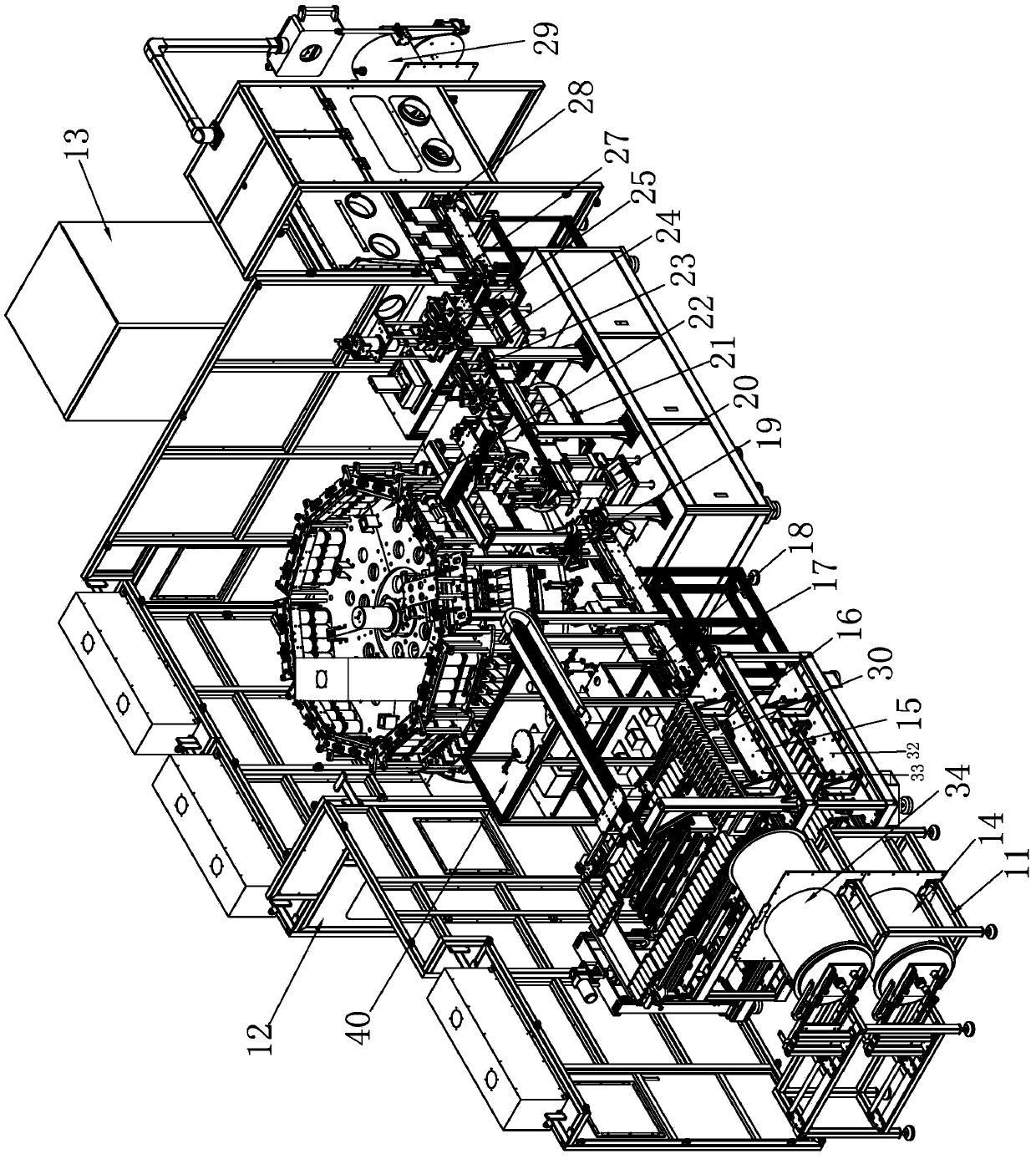
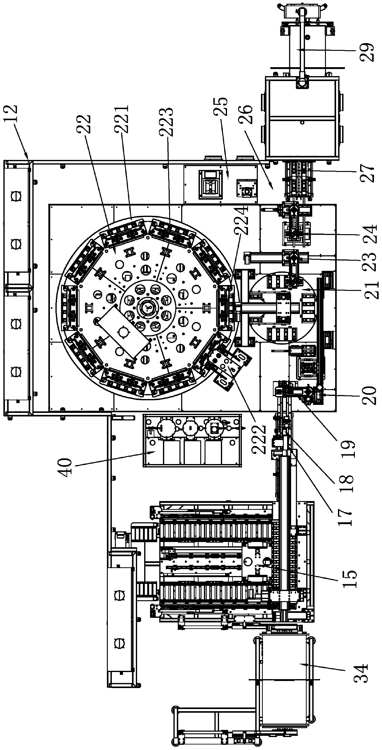
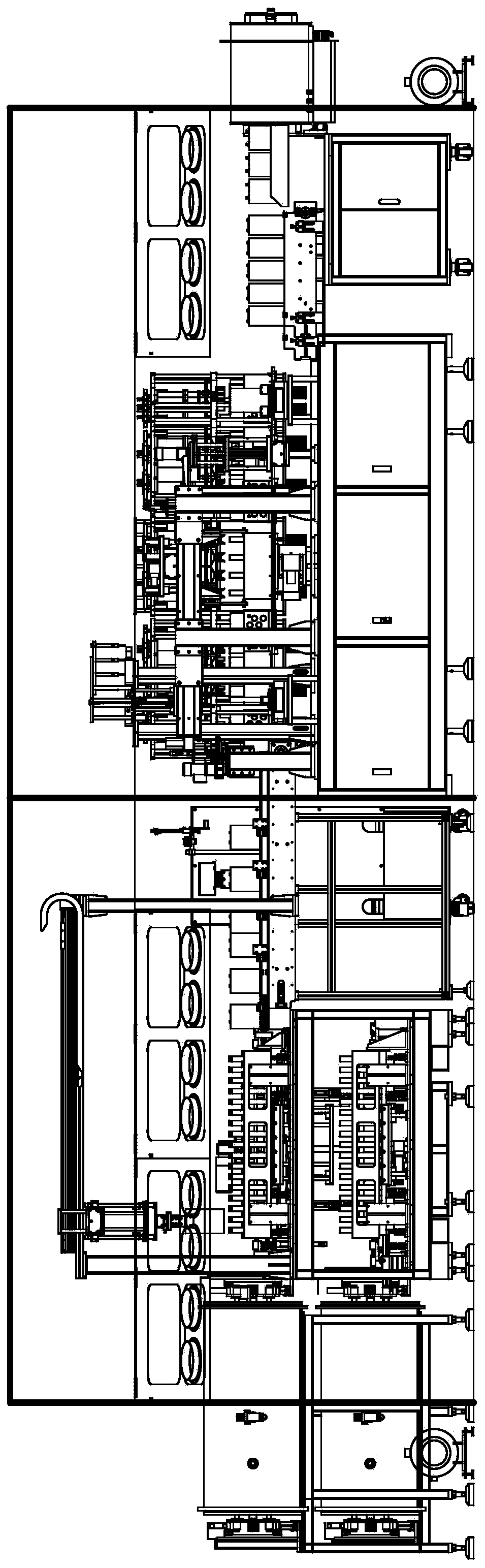
[0071] Please refer to Figure 1 to Figure 13 As shown, it has shown the specific structure of the preferred embodiment of the present invention, the battery automatic liquid injection equipment includes a frame 11, a closed box 12 that is covered outside the frame 11, and is independently arranged in the closed box. The electric control box 13 outside 12 and the vacuum transition cabin 14, drying and cooling mechanism 15, feeding manipulator 16, feeding conveyor belt 17, insulation resistance testing mechanism 18, Loading scanning code weighing manipulator 19, weighing mechanism before liquid injection 20, turntable feeding mechanism 21, liquid injection circulation static turntable mechanism 22, unloading scanning code weighing manipulator 23, weighing mechanism after liquid injection 24, rehydration Station 25, rubber plug station 26, blanking conveyor belt 27, blanking transfer tray 28 and blanking vacuum transition cabin 29, and also includes a drying tray 30 for carrying...


PUM


Abstract

The invention discloses automatic electrolyte injection equipment for batteries. The automatic electrolyte injection equipment comprises a stander, a closed box body covering the stander, an electric cabinet independently arranged outside the closed box body, as well as a loading vacuum transition cabin, a drying and cooling mechanism, a loading manipulator, a loading conveyer belt, an insulation resistance test mechanism, a loading code-scanning and weighing manipulator, a pre-injection weighing mechanism, a turntable loading mechanism, an injection electrolyte circulation standing turntable mechanism, an unloading code-scanning and weighing manipulator, a post-injection weighing mechanism, an electrolyte supplement station, a rubber plug insertion station, an unloading conveyor belt, an unloading transfer tray and an unloading vacuum transition cabin which are sequentially arranged on the stander along the battery conveying direction, and the automatic electrolyte injection equipment further comprises a drying tray used for bearing a battery. Therefore, through the cooperation of each part, the whole automation degree of the equipment is improved, and the production efficiency is greatly improved; meanwhile, the equipment ensures that no bubble exists in the injected electrolyte, realizes stable and reliable electrolyte injection, improves the battery quality and prolongs the service life of the battery.

Description

technical field [0001] The invention relates to the technology in the field of battery production equipment, in particular to an automatic battery liquid injection equipment with a high degree of automation and stable and reliable product quality. Background technique [0002] When making hard-shell lithium batteries, the positive electrode, negative electrode and separator are usually made into pole cores, and then the pole cores are put into the battery shell and covered with a cover plate; usually, a liquid injection hole is provided on the cover plate. The electrolyte is injected into the battery through the liquid injection hole. The quality of the electrolyte and the amount of liquid injection directly determine the quality of the lithium battery. Therefore, the liquid injection is very important. [0003] In the early days, most of them used manual methods. It was difficult to guarantee the dosage of each injection, and manual injection would easily lead to leakage of...

Claims


Application Information

Patent Timeline
Patent Type & Authority Applications(China)
IPC IPC(8): H01M2/36
CPCH01M50/60H01M50/636Y02E60/10
Inventor 喻世民王聪肖江连周元才肖杨
Owner DONGGUAN HONBRO LI BATTERY EQUIP TECH
Why Eureka
Try Eureka