Winding resistance type universal engine spark plug cap

A general-purpose engine, spark plug cap technology, applied in the direction of spark plugs, circuits, electrical components, etc., can solve the problems of difficult cleaning of residues, inconvenient assembly operations, operator burns, etc., to prevent poor product continuity, ensure Reliable, easy-to-clean effect

Inactive Publication Date: 2014-12-24
CHONGQING CONGREN ELECTROMECHANICAL
View PDF6 Cites 0 Cited by
  • Summary
  • Abstract
  • Description
  • Claims
  • Application Information

AI Technical Summary

Problems solved by technology

[0003] 1) The conductive cap is fixed in the main tube of the body by interference fit, which is inconvenient to disassemble and assemble, and the assembly efficiency is low
[0004] 2) The screw has a round head structure, which must be assembled at a high temperature in a hot state (about 150°C). After cooling, the screw can not rotate in the branch pipe; not only that, but the assembly of other parts is also carried out in a hot state. On the one hand, the assembly The process is more complicated, the assembly operation is inconvenient, and the operator is easy to burn his hand; on the other hand, the residue in the body is not easy to clean up, which may easily cause poor conduction of the product
The welding process between the alloy wire and the metal cap is spot welding. Since spot welding is prone to false welding or false welding in the frequent production process, the spot welding between the alloy wire and the metal cap will be damaged during the use of the wirewound resistor. Easy to fall off, resulting in non-conduction of the winding resistor

Method used


Image

  • Winding resistance type universal engine spark plug cap
  • Winding resistance type universal engine spark plug cap
  • Winding resistance type universal engine spark plug cap

Examples


Embodiment Construction

[0019] Below in conjunction with accompanying drawing and embodiment the present invention will be further described:

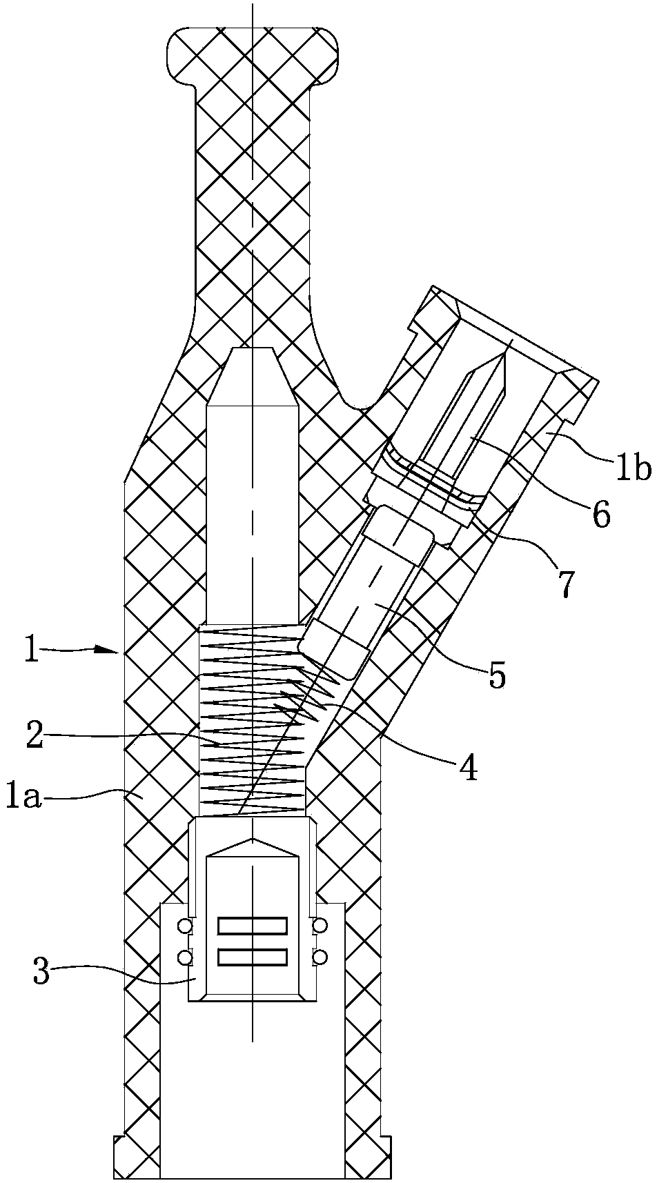
[0020] Such as figure 1 As shown, the main body 1 is formed by injection molding, and is composed of a main pipe 1a and a branch pipe 1b. The body of the main pipe 1a extends obliquely to form a branch pipe 1b, and the angle between the branch pipe 1b and the main pipe 1a is 30°. A main pipe spring 2 and a conductive cap 3 are installed in the main pipe 1a, wherein the inner end of the main pipe spring 2 abuts against the stepped surface in the main pipe 1a, the outer end of the main pipe spring 2 abuts against the conductive cap 3, and the conductive cap 3 abuts against the main pipe 1a. Thread fit.

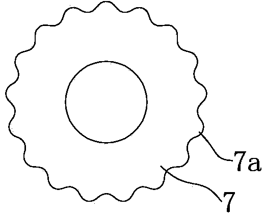
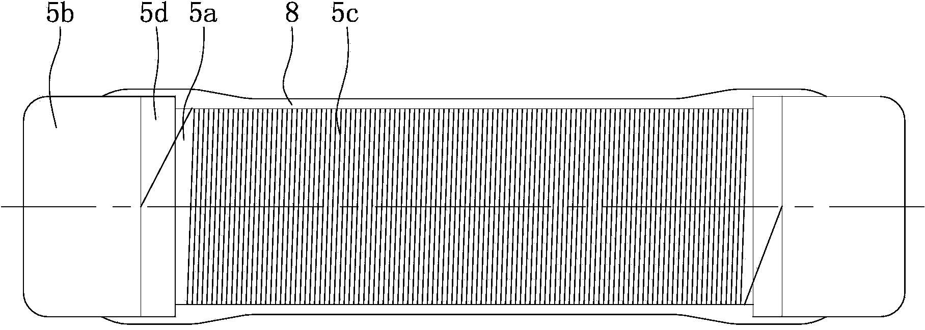
[0021] Such as figure 1 , figure 2 , image 3 As shown, the inner hole of the branch pipe 1b is a three-stage stepped hole with a small inside and a large outside, and a branch pipe spring 4 and a resistor 5 are arranged at the smallest section of the inn...


PUM


Abstract

The invention discloses a winding resistance type universal engine spark plug cap. A main tube spring (2) and a conductive cap (3) are arranged in a main tube (1a), and a branch tube spring (4), a resistor (5) and a screw (6) are sequentially mounted in a branch tube (1b) from inside to outside. The resistor (5) comprises a ceramic stick (5a), metal caps (5b) and an alloy wire (5c). The alloy wire (5c) is wound on a stick body of the ceramic stick (5a), and the ends of the alloy wire (5c) are welded on the corresponding metal caps (5b). The winding resistance type universal engine spark plug cap is simple in process, high in assembling efficiency and capable of being assembled at a normal temperature. An operation worker is prevented from being scalded, remaining objects in a body can be cleaned up easily, and bad conduction of products can be effectively avoided. Silver copper paste is used for attaching the alloy wire and the metal caps, under the premise that the alloy wire is not damaged, the firmness of connection between the alloy wire and the metal cap can be guaranteed, and therefore the conduction performance of a winding resistor is effectively improved.

Description

technical field [0001] The invention relates to an engine component, in particular to a wire-wound resistance spark plug cap on a general engine. Background technique [0002] The wire-wound resistive spark plug cap is an important part of a general-purpose engine. It is used to connect the high-voltage wire and the spark plug. Its quality directly affects the starting performance of the general-purpose engine. Chinese patent ZL 200820098167.6 disclosed a spark plug cap for a general-purpose engine on March 18, 2009. A main pipe spring, a retaining spring and a conductive cap are installed in the main pipe of the body, and branch springs, resistors and screws are installed in the branch pipe of the body. The above structure The disadvantages are: [0003] 1) The conductive cap is fixed in the main tube of the main body by interference fit, which is inconvenient to disassemble and assemble, and the assembly efficiency is low. [0004] 2) The screw has a round head structure...

Claims


Application Information

Patent Timeline
IPC IPC(8): H01T13/04
Inventor 李从仁
Owner CHONGQING CONGREN ELECTROMECHANICAL
Why Eureka
Try Eureka