A Dispersion Measuring System

A measurement system and chromatic dispersion technology, applied in the field of measurement, can solve the problems of unsuitable dispersion of long-distance optical fiber links, difficult implementation, and high system cost, so as to avoid debugging and repeated calibration processes, improve measurement efficiency, and simplify the measurement process. Effect

Inactive Publication Date: 2017-08-25
武汉光盈科技有限公司
View PDF6 Cites 2 Cited by
  • Summary
  • Abstract
  • Description
  • Claims
  • Application Information

AI Technical Summary

Problems solved by technology

[0002] At present, there are many studies on link dispersion measurement of optical transmission systems, such as online dispersion measurement based on time-domain pulse group velocity delay difference detection method. This solution requires the use of high-speed photodetectors, high-sensitivity RF power detectors and Other high-speed auxiliary measurement equipment, and require strict clock synchronization between the transmitting end and the receiving end, the system cost is high, and the accuracy fluctuates greatly, so it is not suitable for the measurement of long-distance optical fiber link dispersion
On-line dispersion monitoring based on time-domain asynchronous sampling method, this type of method requires the use of high-speed photoelectric devices, such as light-speed photodetectors, high-speed analog-to-digital converters, high-speed signal analyzers and other devices or equipment, the system cost is extremely high, and the dispersion measurement The range is limited and the accuracy is not high. It is suitable for monitoring the change of link dispersion within a certain range, but not suitable for the actual measurement of link dispersion. Format-dependent, a scheme can only target a specific modulation format
Dispersion monitoring based on RF spectrum analysis based on phase-sensitive detection, this type of method has similar shortcomings to the above-mentioned schemes, requires high-speed optoelectronic devices and expensive spectrum analysis instruments, the measurement range is too small, and the measurement system is too large to achieve Real-time measurement of dispersion in the optical transmission system; the measurement system has poor anti-noise performance, low measurement accuracy, high system cost, measurement results are greatly affected by device performance, and the consistency of multiple measurement results is poor, resulting in extremely low efficiency

Method used


Image

  • A Dispersion Measuring System
  • A Dispersion Measuring System
  • A Dispersion Measuring System

Examples


Embodiment 1

[0034] A method for measuring dispersion provided by an embodiment of the present invention is used for measuring the dispersion value of an optical fiber link; it is characterized in that it includes the following steps:

[0035] Generate an optical carrier signal through a stable continuous light source;

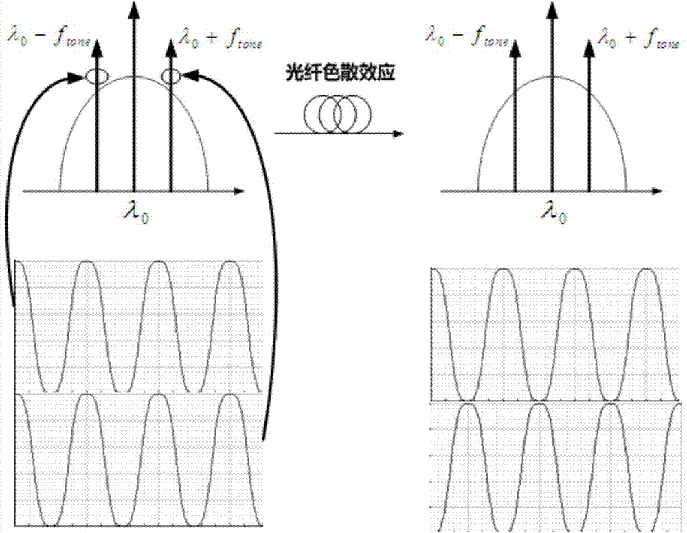
[0036] The optical carrier signal is modulated into a double-sided band optical spectrum by using a radio frequency signal;

[0037] Send the double sideband optical spectrum to the optical fiber link to be tested;

[0038] Photoelectrically convert the optical signal at the output end of the optical fiber link to be tested into an electrical signal, and monitor the power value of the electrical signal in real time;

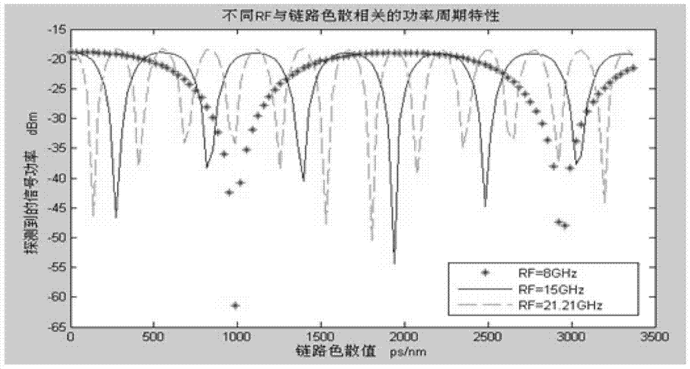
[0039] Adjust the scanning frequency of the radio frequency signal to determine the scanning frequency f of the minimum power of the electrical signal null ;

[0040] Calculate the scan frequency f null The dispersion value when .

[0041] In this embodi...

Embodiment 2

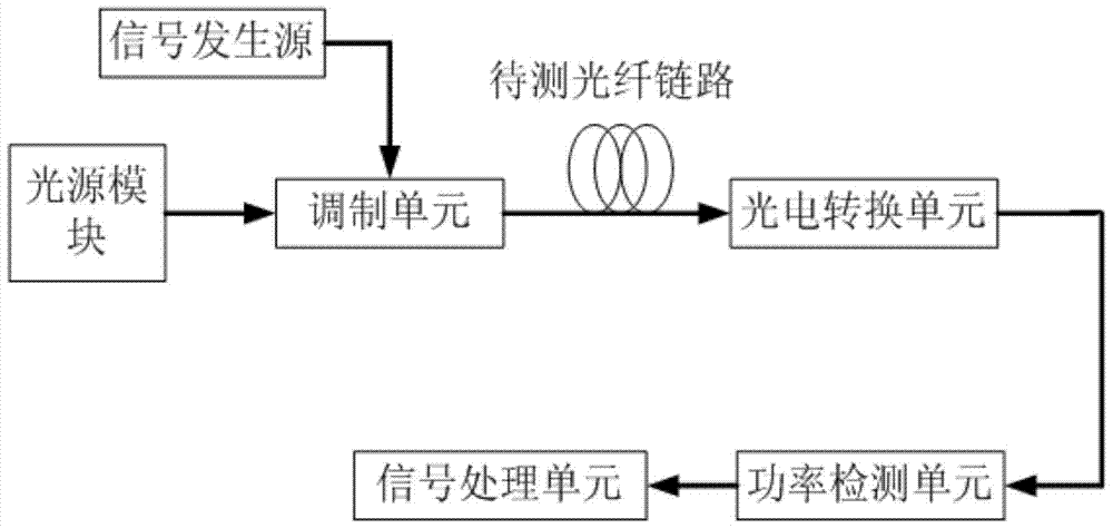
[0055] see Figure 7 , this embodiment provides a dispersion measurement system based on the measurement method of Embodiment 1, which is used for dispersion value measurement of optical fiber links; including: a light source module, a signal generation source, a modulation unit, a photoelectric conversion unit, a power detection unit and a signal processing unit;

[0056] The light source module generates an optical carrier signal; the signal generation source generates a radio frequency signal, and modulates the optical carrier signal through the modulation unit to generate a double-sideband optical spectrum signal; the double-sideband optical spectrum signal is connected to the optical fiber link to be tested and sent to The photoelectric conversion unit realizes the conversion of the optical signal to the electrical signal; the power detection unit receives and measures the power of the electrical signal, and sends the measured value to the signal processing unit for analy...

Embodiment 3

[0066] see Figure 8 , with respect to embodiment two, present embodiment increases on the basis of embodiment two: optical fiber amplifier, band-pass optical filter and band-pass electric filter; Optical fiber amplifier is connected between modulation unit and optical fiber link to be tested; Improve detection The input power of the signal can ensure the amplitude of the measured signal and reduce the observation error. The band-pass optical filter is connected between the output end of the optical fiber link to be tested and the photoelectric conversion unit to filter out optical clutter and avoid interference with the measurement; the band-pass electrical filter is connected between the photoelectric conversion unit and the power detection unit to filter out Electrical clutter, to avoid interference with the measurement.


PUM


Abstract

The invention belongs to the technical field of measurement, and discloses a dispersion measuring method. The dispersion measuring method is used for measuring a dispersion value of an optical fiber link and is characterized by comprising the following steps of generating an optical carrier signal through a stable and continuous light source, adopting a radio-frequency signal for modulating the optical carrier signal into a double-sideband optical spectrum, sending the double-sideband optical spectrum to the optical fiber link to be measured, conducting photovoltaic conversion on an optical signal at the output end of the optical fiber link to be measured to convert the optical signal into an electric signal, monitoring the power value of the electric signal in real time, adjusting the scanning frequency of the radio-frequency signal, determining the scanning frequency fnull generated when the power of the electric signal is the minimum, and calculating a dispersion value obtained when the scanning frequency fnull is generated. According to the dispersion measuring method, the double-sideband optical spectrum detects the optical signal and is sent to the optical fiber link to be measured and then converted into periodical power changes of the electric signal, accurate positioning is achieved, data sampling is optimized, and therefore the measuring precision is improved; then the measuring frequency is reduced, efficiency is improved, and the measurement range is extended.

Description

technical field [0001] The invention relates to the technical field of measurement, in particular to a dispersion measurement system. Background technique [0002] At present, there are many studies on link dispersion measurement of optical transmission systems, such as online dispersion measurement based on time-domain pulse group velocity delay difference detection method. This solution requires the use of high-speed photodetectors, high-sensitivity RF power detectors and Other high-speed auxiliary measurement equipment requires strict clock synchronization between the transmitting end and the receiving end. The system cost is high and the accuracy fluctuates greatly. It is not suitable for the measurement of long-distance optical fiber link dispersion. On-line dispersion monitoring based on time-domain asynchronous sampling method, this type of method requires the use of high-speed photoelectric devices, such as light-speed photodetectors, high-speed analog-to-digital con...

Claims


Application Information

Patent Timeline
Patent Type & Authority Patents(China)
IPC IPC(8): H04B10/07
Inventor 李斌
Owner 武汉光盈科技有限公司
Why Eureka
Try Eureka