Linear high voltage LED driving circuit

A technology of LED drive and circuit, applied in electric lamp circuit arrangement, electric light source, lighting device, etc., can solve the problems of low luminous efficiency, low power utilization rate, power consumption, etc.

Active Publication Date: 2014-12-24
SHAANXI REACTOR MICROELECTRONICS
View PDF3 Cites 11 Cited by
  • Summary
  • Abstract
  • Description
  • Claims
  • Application Information

AI Technical Summary

Problems solved by technology

In this application, only when the output voltage of the rectifier bridge stack is higher than the conduction voltage of the LED string, the LED string will emit light normally; and when the output voltage of the rectifier bridge stack is lower than the conduction voltage of the LED string, most of the power will be consumed On the constant curr

Method used


Image

  • Linear high voltage LED driving circuit
  • Linear high voltage LED driving circuit
  • Linear high voltage LED driving circuit

Examples


Embodiment Construction

[0029] In order to make the purpose, technical solutions and advantages of the present invention clearer, the technical solutions in the present invention will be clearly and completely described below in conjunction with the accompanying drawings in the present invention. Obviously, the described embodiments are part of the embodiments of the present invention , but not all examples. Based on the embodiments of the present invention, all other embodiments obtained by persons of ordinary skill in the art without creative efforts fall within the protection scope of the present invention.

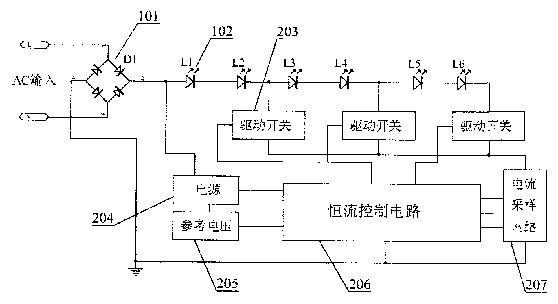
[0030] attached figure 2 It is a structural schematic diagram of a multi-segment linear high-voltage LED drive circuit of the present invention; as figure 2As shown, it includes: a rectifier bridge stack 101, an LED string 102, a drive switch 203 for driving the LED string 102 to conduct, a constant current control circuit 206 for controlling the conduction impedance of each drive switch, ...


PUM


Abstract

The invention provides a linear high voltage LED driving circuit comprising a rectifier bridge pile, two or more LED strings, driving switches matched with the LED strings, a current sampling circuit used for detecting current of each driving switch, and a constant current control circuit used for controlling each driving switch to conduct a resistant; the constant current control circuit and the driving switches are used for controlling the at least two LED strings to be partially or fully conducted for illumination according to the changes of the DC pulse voltage, so conducted illumination time of the LED string can be improved in one voltage pulse period, and power consumption of the driving switches is reduced, thus greatly improving LED driving efficiency.

Description

technical field [0001] The invention belongs to the technical field of light emitting diode (Light Emitting Diode, hereinafter referred to as: LED) lighting technology, and in particular relates to a linear high-voltage LED driving circuit. Background technique [0002] At present, the LED lighting power supply mainly adopts switching power supply, which has the advantages of high efficiency and small size. However, the switching power supply also has shortcomings that are difficult to overcome. The specific performance is: because the switching power supply uses electrolytic capacitors and transformers or inductors, the biggest disadvantage of electrolytic capacitors is short life and low reliability, and its service life can only reach 5000 at most. -8000 hours; and the service life of aluminum electrolytic capacitors will generally decrease by 10% for every 10°C increase in operating temperature, and the operating temperature of switching power supplies for LED lights is ...

Claims


Application Information

Patent Timeline
IPC IPC(8): H05B37/02
CPCY02B20/40
Inventor 杨波杨世红
Owner SHAANXI REACTOR MICROELECTRONICS
Why Eureka
Try Eureka