Eardrum acoustic pressure detection method and eardrum acoustic pressure detection system

A detection method and tympanic membrane technology, applied in audiometers and other directions, can solve the problems of subject shaking, inaccurate measurement results, narrow application range, etc., and achieve the effects of improved frequency resolution, improved detection efficiency, and wide application range

Active Publication Date: 2014-12-31
SHENZHEN INST OF ADVANCED TECH
View PDF5 Cites 7 Cited by
  • Summary
  • Abstract
  • Description
  • Claims
  • Application Information

AI Technical Summary

Problems solved by technology

[0006] However, the main disadvantages of the probe measurement method are: (1) Use pure tone (fixed frequency sine wave) to measure limited frequency points, and the measured frequency points are far apart (generally measure 0.5, 1, 2, 3, 4, 5 , 6, 8kHz and other standard frequencies), the measurement time for the entire hearing frequency range is long, and the frequency resolution and detection efficiency are not high; Strong discomfort, the micro-probe has potential damage to the tympanic membrane, and long-term measurement can easily cause the subject to shake slightly, which will cause the probe to move and the measurement r

Method used


Image

  • Eardrum acoustic pressure detection method and eardrum acoustic pressure detection system
  • Eardrum acoustic pressure detection method and eardrum acoustic pressure detection system
  • Eardrum acoustic pressure detection method and eardrum acoustic pressure detection system

Examples


Embodiment Construction

[0069] The technical solution of the method and system for detecting the sound pressure of the eardrum will be described in detail below in conjunction with specific embodiments and accompanying drawings, so as to make it more clear.

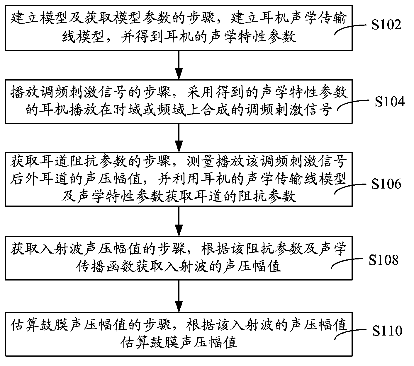
[0070] like figure 1 As shown, it is a flowchart of a method for detecting sound pressure of an eardrum in an embodiment. The tympanic membrane sound pressure detection method includes:

[0071] Step S102, the step of establishing a model and obtaining model parameters, establishing an acoustic transmission line model of the earphone, and obtaining the acoustic characteristic parameters of the earphone.

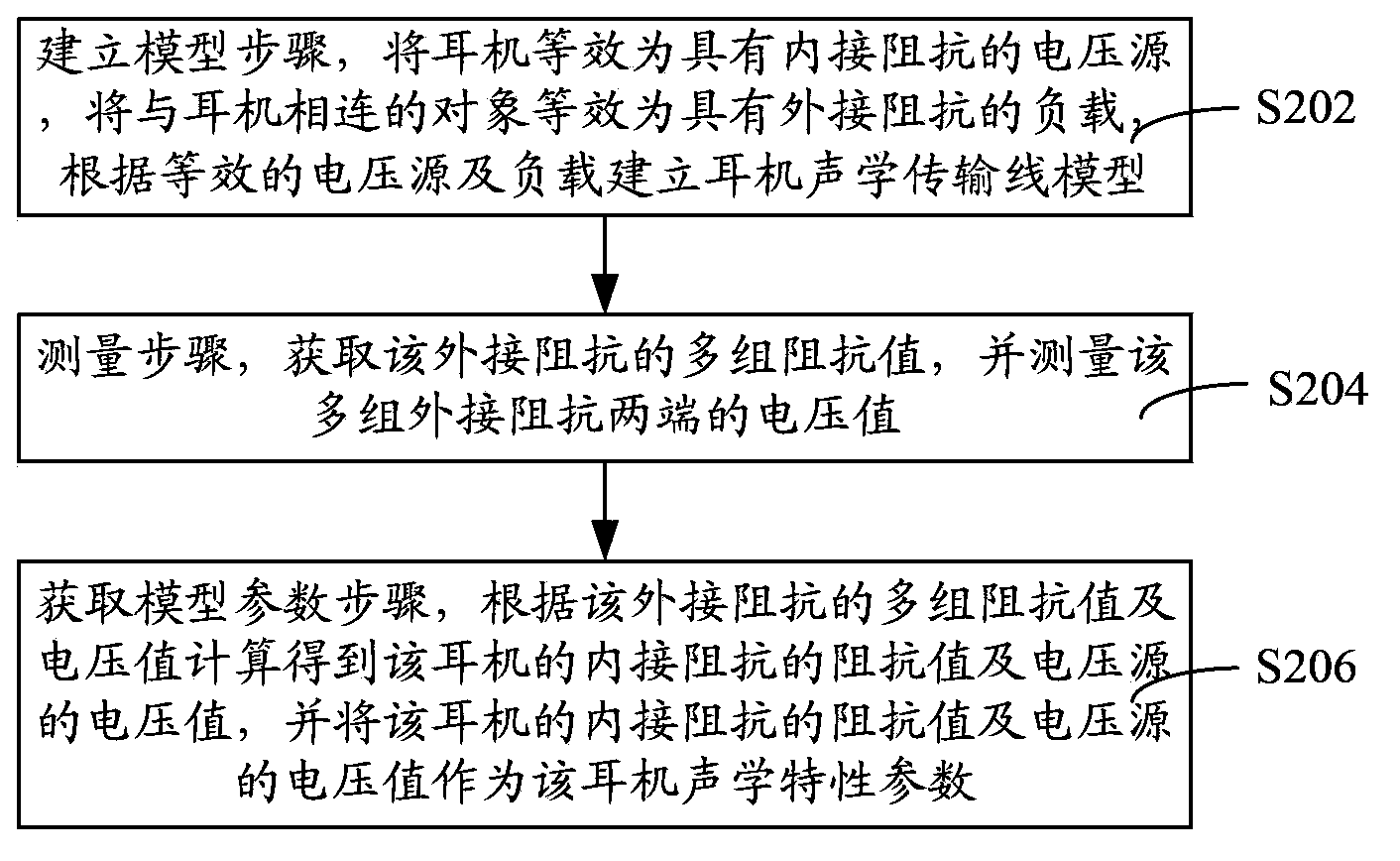
[0072] In one embodiment, such as figure 2 As shown, step S102 includes:

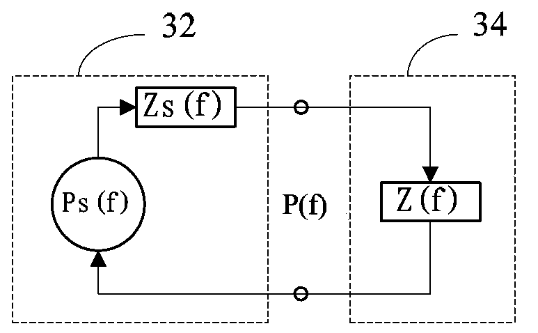
[0073] Step S202, the modeling step, the earphone is equivalent to a voltage source with internal impedance, the object connected to the earphone is equivalent to a load with external impedance, and the acoustic transmission line model of the earphone is established ...


PUM


Abstract

The invention relates to an eardrum acoustic pressure detection method and an eardrum acoustic pressure detection system. The method comprises the following steps: establishing an earphone acoustic transmission line model and acquiring acoustic characteristic parameters of an earphone; playing a frequency-modulated stimulation signal synthesized in a time domain or a frequency domain by use of the obtained earphone with the acoustic characteristic parameters; measuring an acoustic pressure amplitude value of an external auditory canal after the frequency-modulated signal is played, and acquiring impedance parameters of the auditory canal by use of the acoustic transmission line model and acoustic characteristic parameters of the earphone; acquiring the acoustic pressure amplitude value of incident waves according to the impedance parameters and an acoustic propagation function; estimating an eardrum acoustic pressure amplitude value according to the acoustic pressure amplitude value of the incident waves. According to the eardrum acoustic pressure detection method and the eardrum acoustic pressure detection system, the frequency-modulated stimulation signal in the time domain or frequency domain is utilized for measurement, so that acoustic pressures within a wide frequency range can be detected in one step, the detection efficiency is improved, influence of individual difference is avoided, the detection method and the detection system are wide in application range, the detection result accuracy is high, and the frequency resolution and the detection security are improved.

Description

technical field [0001] The invention relates to acoustic detection technology, in particular to a method and system for detecting sound pressure of an eardrum. Background technique [0002] The auditory system is one of the five sensory systems of human beings, and it is an important channel for human beings to perceive and understand the sound world around them. The human auditory system perceives sound as follows: the outer ear collects sound waves, passes through the ear canal to the tympanic membrane, and the tympanic membrane converts sound energy (changes in air pressure) into its own vibrations. The vibrations are transmitted by the ossicles to the fluid-filled cochlea, where vibrations in the hair cells inside the cochlea cause nerve impulses. These impulses are transmitted from the auditory nerve to the auditory center, and finally analyzed and interpreted by the auditory cortex as meaningful sound information. Part of the sound energy entering the ear canal will ...

Claims


Application Information

Patent Timeline
IPC IPC(8): A61B5/12
Inventor 陈世雄邓军田岚魏征匡星李光林
Owner SHENZHEN INST OF ADVANCED TECH
Why Eureka
Try Eureka