
Grinding and recovering system

A recovery system and absorption tank technology, applied in grinding/polishing equipment, grinding/polishing safety devices, metal processing equipment, etc., can solve problems such as easy generation of high temperature, increased power consumption of air conditioners, negative pressure in grinding workshops, etc. Achieve the effect of avoiding waste and saving electricity

Inactive Publication Date: 2014-12-31
CHOW SANG SANG JEWELRY
View PDF4 Cites 2 Cited by
  • Summary
  • Abstract
  • Description
  • Claims
  • Application Information

AI Technical Summary

Problems solved by technology

[0002] The entrance of the outer cover in the existing grinding and recycling system is open, which may easily cause the grinding debris or precious metal shavings to escape out of the recycling box during grinding, and there is no way to recycle, resulting in waste of materials
The total air volume of the central vacuum cleaner connected to the recovery box is huge (about 7,200 cubic meters per hour), causing severe negative pressure in the grinding workshop, and the continuous loss of indoor cold air increases the temperature of the grinding workshop and increases power consumption
In addition, the motor used in the grinding machine is generally an electric motor, and the continuous operation of the electric motor is likely to generate high temperature, causing the temperature in the working room to rise, increasing the operating intensity of the air conditioner in the working room, and increasing the power consumption of the air conditioner

Method used


Image

  • Grinding and recovering system
  • Grinding and recovering system
  • Grinding and recovering system

Examples


Embodiment 1

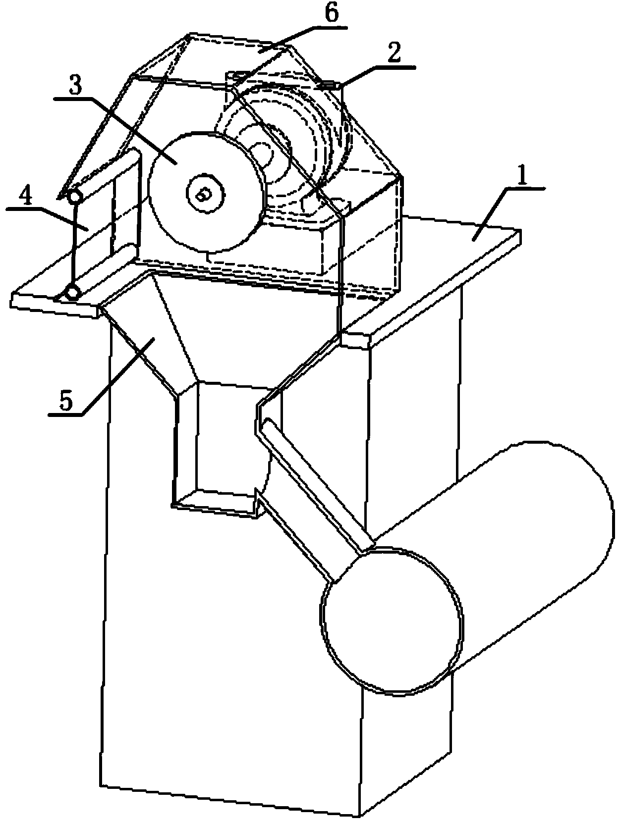
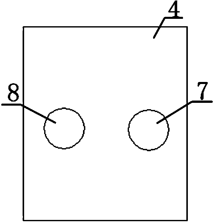
[0025] figure 1 and figure 2 A schematic cross-sectional structure diagram of the grinding recovery system and a schematic structural diagram of the air curtain are shown respectively. Such as figure 1 As shown, the air curtain 4 is connected to the outer cover 6 to seal the entrance of the outer cover 6, and the air curtain 4 is a plexiglass plate or a hard plastic plate. The air curtain 4 is provided with a working inlet, so that the hands of the staff can reach into the outer cover 6 for grinding operation, and the number of inlets can be set to one or two. Such as figure 2 As shown, the air curtain 4 is provided with a first inlet 7 and a second inlet 8 as working inlets. In the working state, the air motor 2 drives the rotating wheel 3 to rotate, the staff member puts his right hand into the first inlet 7, his left hand into the second inlet 8, and passes through the The runner 3 grinds the grinding object, and the grinding debris is recovered to the central recove...

Embodiment 2

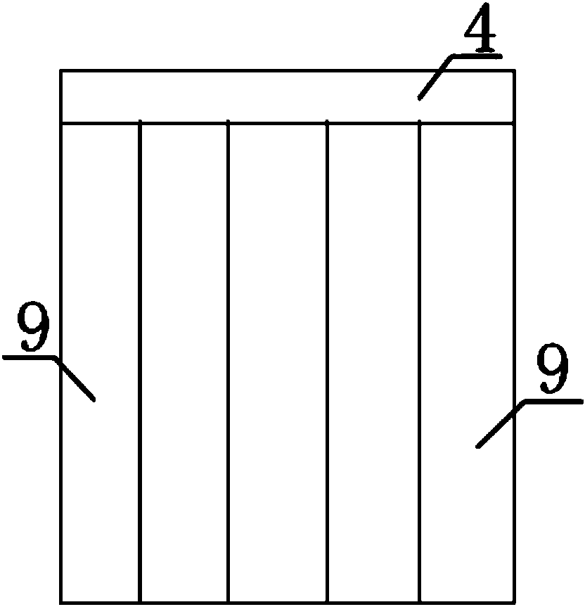
[0027] figure 1 and image 3 A schematic cross-sectional structure diagram of the grinding recovery system and a schematic structural diagram of the air curtain are shown respectively. Such as figure 1 As shown, the air curtain 4 is connected to the outer cover 6 to seal the opening of the outer cover 6, as image 3 As shown, the air curtain 4 is composed of soft plastic strips 9, the upper ends of the soft plastic strips 9 are connected to each other, the lower ends hang down naturally, and the gap between adjacent plastic strips can form a working entrance. In the working state, the air motor 2 drives the runner 3 to rotate, and the staff's hands extend into the outer cover 6 through the gap between the soft plastic strips 9 and pass through the runner 3 The grinding object is ground, and the grinding debris is recovered to the central recovery box through the absorption tank 5 . The air curtain 4 prevents the grinding debris from leaking out of the outer cover 6 , which...


PUM


Abstract

The invention discloses a grinding and recovering system which comprises an outer frame, a motor, a rotating wheel, an air curtain, an absorbing groove and an outer cover. The motor, the rotating wheel, the air curtain, the absorbing groove and the outer cover are arranged on the outer frame, the rotating wheel is positioned in the outer cover and fixedly connected with a rotating shaft of the motor, the absorbing groove is arranged below the rotating wheel, an inlet is arranged between the outer cover and the outer frame, the air curtain and the outer cover are connected to seal the inlet, and a working inlet is arranged on the air curtain. The air curtain is arranged, so that chippings or precious metal particles during grinding are prevented from leaking to the outside of the absorbing groove, and avoiding of material waste is facilitated; a pneumatic motor is adopted to replace an original electric motor, and the pneumatic motor which works continuously does not generate high temperature, so that an air conditioner of a work room is enabled to normally run, and electricity is saved.

Description

technical field [0001] The invention relates to a grinding recovery system. Background technique [0002] The entrance of the outer cover in the existing grinding recovery system is open, and it is easy to cause grinding debris or precious metal shavings to run out of the recovery box during grinding, and there is no way to recycle, resulting in waste of materials. The total air volume of the central vacuum cleaner connected to the recycling bin is huge (approximately 7,200 cubic meters per hour), causing severe negative pressure in the grinding workshop. The continuous loss of indoor cold air increases the temperature of the grinding workshop and increases power consumption. In addition, the motor used in the grinder is generally an electric motor, and the continuous operation of the electric motor is likely to generate high temperature, causing the temperature in the working room to rise, increasing the operating intensity of the air conditioner in the working room, and in...

Claims


Application Information

Patent Timeline
Patent Type & Authority Applications(China)
IPC IPC(8): B24B55/12
CPCB24B55/12
Inventor 黄宏耀林国伟
Owner CHOW SANG SANG JEWELRY
Learn More