
Injection molding module and injection molding method

A technology of injection molding and modules, which is applied in the field of injection molding modules, can solve the problems of time-consuming processing costs, scratches, drops, etc., and achieve the effect of reducing the length of residual glue

Inactive Publication Date: 2014-12-31
WISTRON CORP
View PDF6 Cites 3 Cited by
  • Summary
  • Abstract
  • Description
  • Claims
  • Application Information

AI Technical Summary

Problems solved by technology

[0004] However, because a large amount of fiber material is often added to plastics in the injection molding process in recent years, a new problem has never occurred in plastics without fiber materials: when the plastic enters the mold cavity 13 from the cold runner 14, the fiber material will Constantly impact the inner side of the master mold 12 to face the cold runner 14 ( figure 1 (marked with A in the center), the inner surface of the master mold 12 is scratched, resulting in defects like white mist in the appearance of the final product after molding, which cannot meet the production requirements for a bright and smooth surface of the finished product.
In addition, after the inner surface of the master mold 12 is scratched, the entire injection molding process will be forced to stop for repairing the injection molding module 1, which will not only require extra time and manpower, but will also stop the production line and reduce production capacity.
In addition, because in the existing injection molding module 1, the cold runner 14 extends from the outside of the injection molding module 1 to the mold cavity 13 in a single direction, so after the finished product is cooled and molded, a section of the cold runner 14 will be formed. A rather long residual material needs to be reprocessed to remove the residual material, which is not only time-consuming but also generates an additional processing cost

Method used


Image

  • Injection molding module and injection molding method
  • Injection molding module and injection molding method
  • Injection molding module and injection molding method

Examples


Embodiment Construction

[0038] The aforementioned and other technical contents, features and effects of the present invention will be clearly presented in the following detailed description of the embodiments with reference to the accompanying drawings.

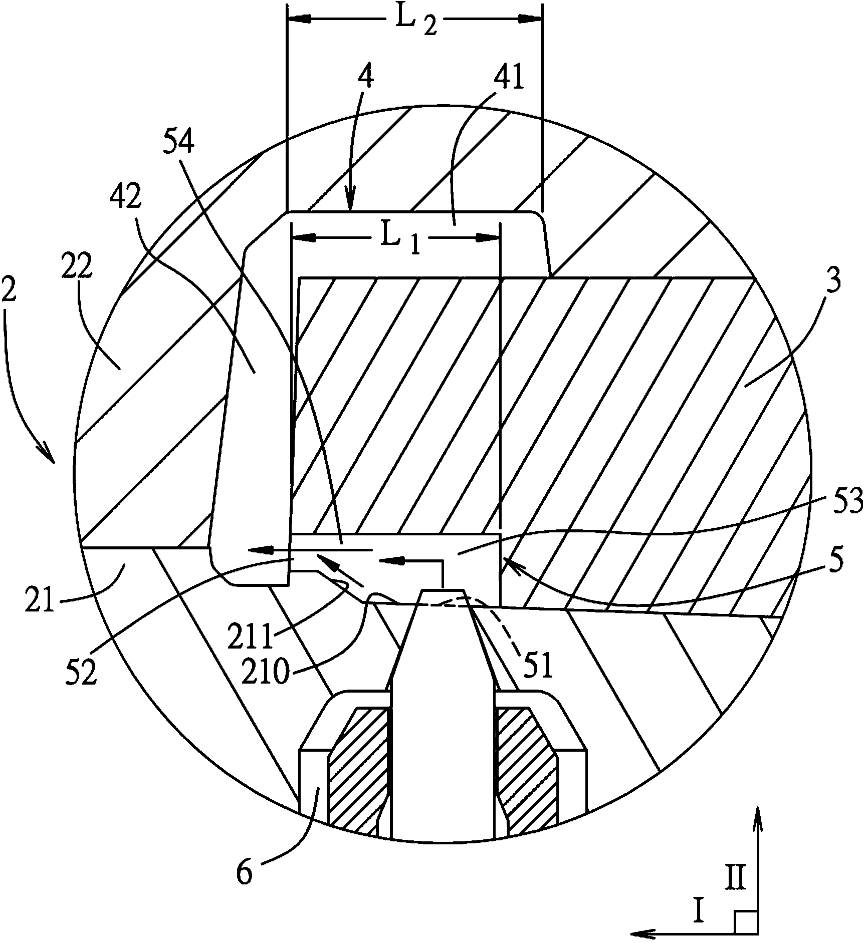
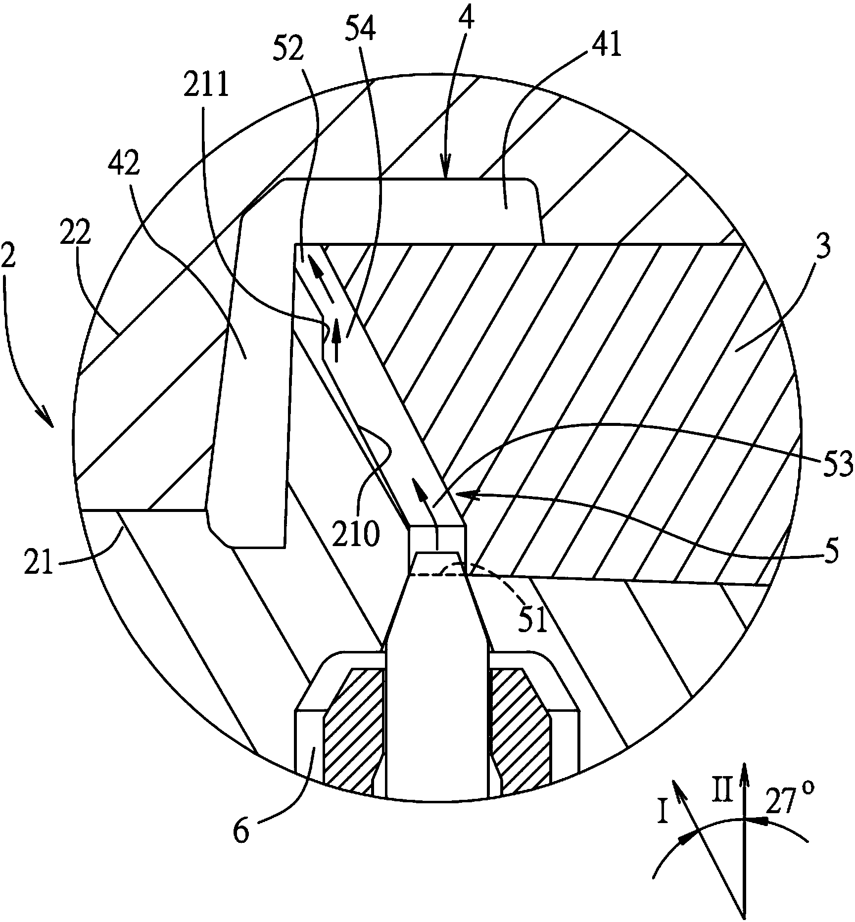
[0039] refer to figure 2 , is the first embodiment of the injection molding module of the present invention. The injection molding module includes a mold 2 , a slider 3 inside the mold 2 , a mold cavity 4 , and a cold runner 5 . The mold 2 includes a first mold 21 and a second mold 22 . The mold cavity 4 is defined by cooperation of the first mold 21 and the second mold 22 with the slider 3 . The first mold 21 has an inner wall surface 210 . The slide block 3 cooperates with the inner wall surface 210 of the first mold 21 to define the cold runner 5 . The inner wall surface 210 has a slope area 211 . The mold cavity 4 is used to form a finished product and includes a finished main wall area 41 and a finished side wall area 42 . The slider 3 c...


PUM

PropertyMeasurementUnit
lengthaaaaaaaaaa

Abstract

The invention relates to an injection molding module and an injection molding method. The injection molding module includes a mold unit and a slider that is disposed in the mold unit and that cooperates with the mold unit to define a cavity and a cooling runner in spacial communication with the cavity. The cavity is used to mould finished products and includes a moulded product main wall area and a moulded product sidewall area. The cooling runner comprises an inlet for feeding plastics, discharge outlet communicating with the moulded product main wall area, a main section between the inlet and the outlet and a tapering section that extends from one end of the main section to the outlet in a lengthwise direction and tapers towards the outlet direction. The opening direction of the inlet is not parallel to the length direction, so that the plastic material having a flow direction that is changed when a plastic material is fed into the cooling runner through the inlet. The injection molding module and the injection molding method prevent defects on the surface of the finished products and scratching of the inner surfaces of the die.

Description

technical field [0001] The present invention relates to an injection molding module, in particular to an injection molding module which avoids surface contamination defects caused by fiber materials in plastics, and an injection molding method of the injection molding module. Background technique [0002] In recent years, in the plastic injection molding process, in order to improve the rigidity, surface smoothness, and brightness of the finished product, a large amount of fiber materials (such as glass fiber or carbon fiber, etc.) Meet the needs of consumers. [0003] refer to figure 1 , is an existing injection molding module 1, the injection molding module 1 includes a male mold 11 and a female mold 12 assembled with each other, and a cavity 13 defined by the male mold 11 and the female mold 12. The male mold 11 is provided with a cold runner 14 connecting the mold cavity 13 and the outside of the injection molding module 1 . During injection molding, the plastic is in...

Claims


Application Information

Patent Timeline
Patent Type & Authority Applications(China)
IPC IPC(8): B29C45/27
CPCB29C45/2756B29C44/582B29C44/585B29C45/33B29C45/585B29C45/0005B29C45/18B29C45/26B29C45/27
Inventor 林源祥蔡建宏洪安镇
Owner WISTRON CORP
Features
  • Generate Ideas
  • Intellectual Property
  • Life Sciences
  • Materials
  • Tech Scout
  • Unparalleled Data Quality
  • Higher Quality Content
  • 60% Fewer Hallucinations
Learn More