Anti-electrostatic heater plate structure

An anti-static, hot plate technology, applied in the direction of circuits, electrical components, optics, etc., can solve the problems of not eliminating the influence of static electricity, fragmentation, yield loss, etc., and achieve the effect of eliminating the influence of static electricity and improving the problem of fragmentation

Inactive Publication Date: 2014-12-31
EVERDISPLAY OPTRONICS (SHANGHAI) CO LTD
View PDF1 Cites 9 Cited by
  • Summary
  • Abstract
  • Description
  • Claims
  • Application Information

AI Technical Summary

Problems solved by technology

The technical problem to be solved is that, if the electrostatic attraction force during the lift-off process is large enough, the excessive bowing of the substrate occurs before the substrate is completely detached from the substrate support
[0005] However, this prior art, such as Figure 5 As shown, the glass substrate 140 still deforms within 2mm of the height difference between the li

Method used


Image

  • Anti-electrostatic heater plate structure
  • Anti-electrostatic heater plate structure
  • Anti-electrostatic heater plate structure

Examples


Embodiment Construction

[0035] Typical embodiments that embody the features and advantages of the present invention will be described in detail in the following description. It should be understood that the present invention is capable of various changes in different embodiments without departing from the scope of the present invention, and that the description and drawings therein are illustrative in nature and not limiting. this invention.

[0036] As used in the specification and drawings, the singular forms "a", "an" and "the" include plural references unless the content clearly dictates otherwise. The foregoing and other technical contents, features and effects of the present disclosure will be clearly presented in the following detailed description of a preferred embodiment with reference to the drawings. The directional terms mentioned in the following embodiments, such as: up, down, left, right, front or back, etc., are only directions referring to the attached drawings. Accordingly, the di...


PUM

PropertyMeasurementUnit
Heightaaaaaaaaaa

Abstract

The invention provides an anti-electrostatic heater plate structure applied to photoresist coating of flat-plate displays and developer tables. A glass substrate is arranged on the top surface of a heater plate and is heated up by the same. A plurality of jacking rods capable of jacking upwards from the top surface of the heater plate are mounted in the heater plate. A plurality of fixed jacking pins arranged at intervals are disposed on the top surface of the heater plate and used for supporting the glass substrate on the top surface of the heater plate. Compared with the conventional manner of directly attaching the glass substrate onto the surface of the heater plate, the manner of utilizing the jacking pins to jack the glass substrate by 0.1MM can not only eliminate electrostatic influences of the heater plate but eliminate influences to heat radiation conduction.

Description

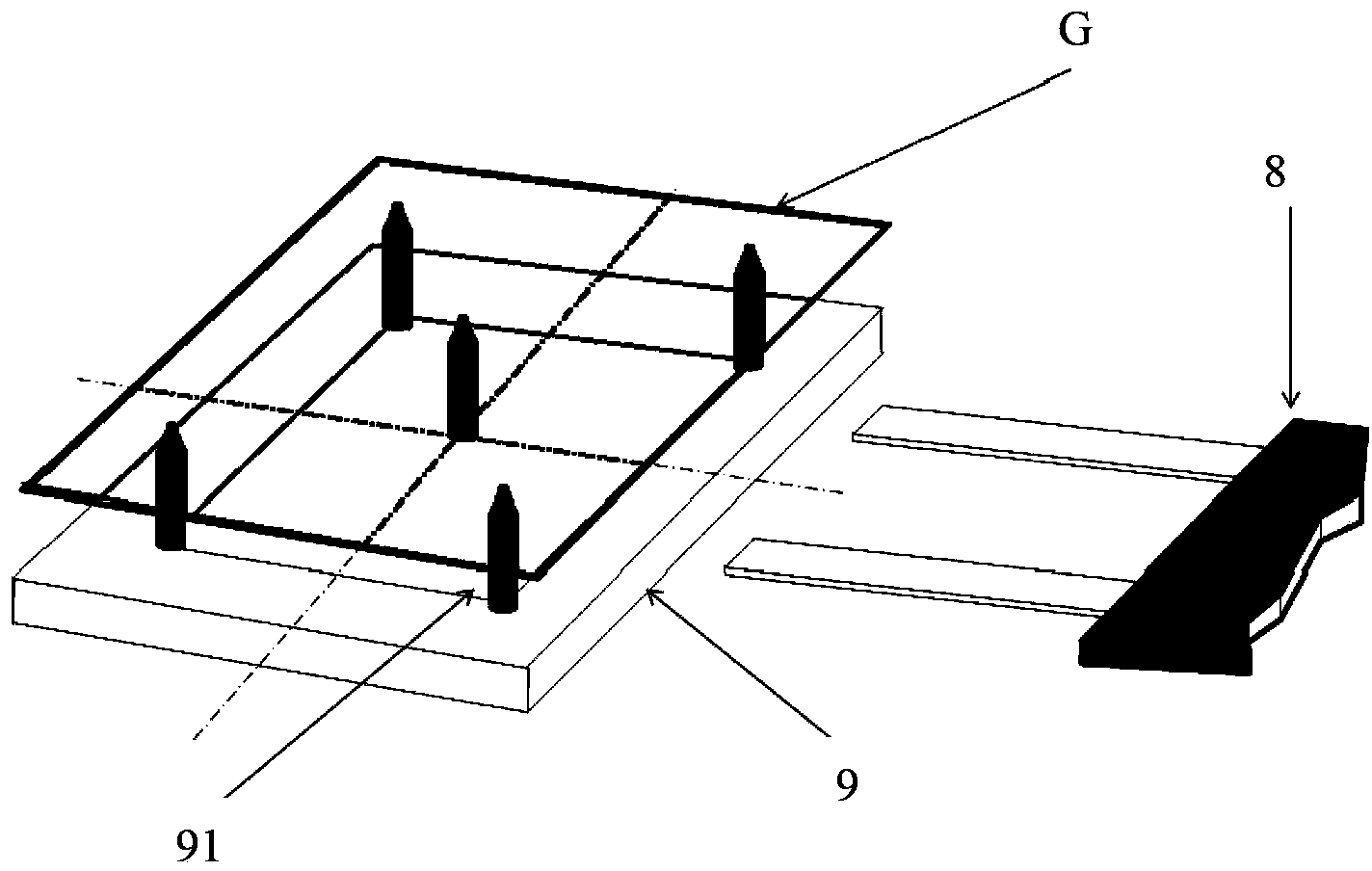
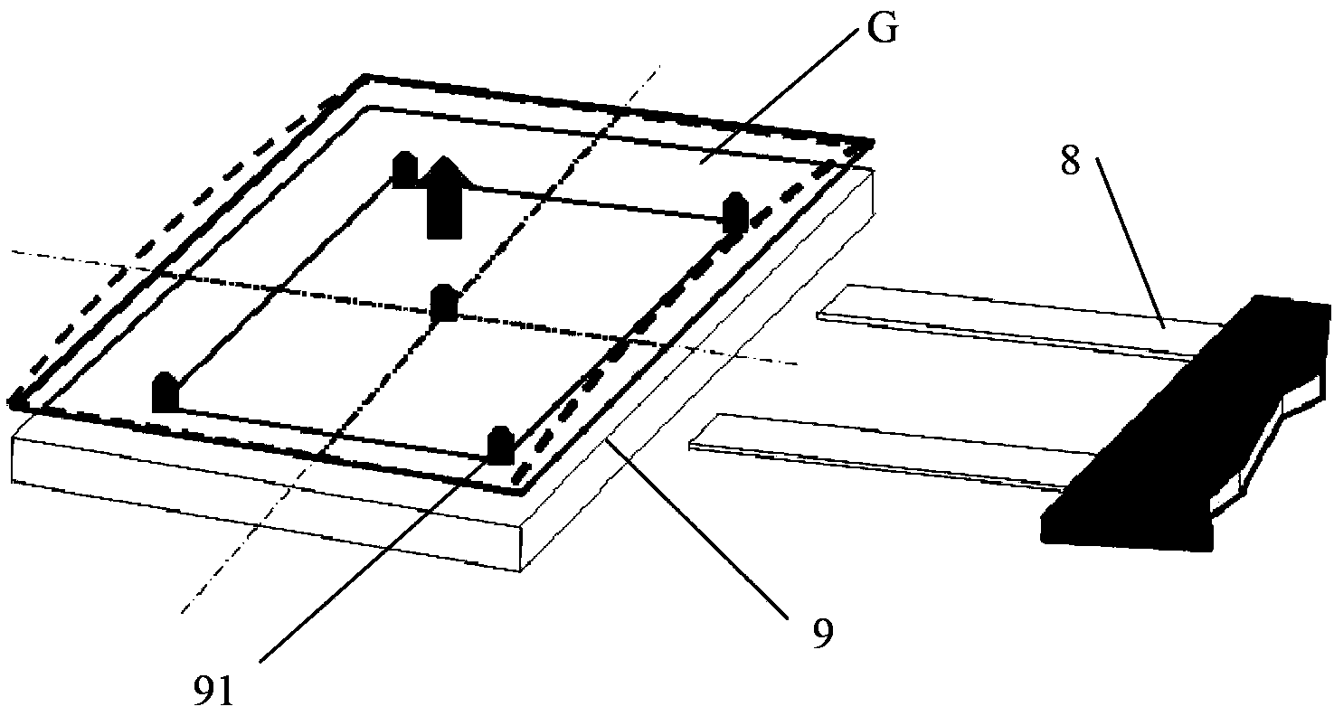
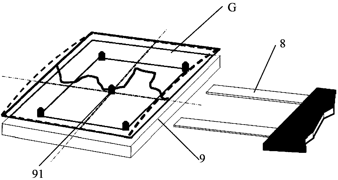
technical field [0001] The invention relates to display screen manufacturing equipment, in particular to an antistatic hot plate structure capable of ensuring the reliability of OLEDs. Background technique [0002] Photoresist coating and developing equipment in flat panel display exposure process, such as Figures 1 to 3 As shown, the transfer of the glass substrate G is mainly carried out by the robot arm 8 . In the hot plate structure of the prior art, there is an electric heating device for heating the glass substrate G inside the hot plate 9 . Generally, a heating wire is arranged in the hot plate 9 through a hot groove. A plurality of liftable ejector pins 91 are arranged inside the hot plate 9 . The ejector pins 91 distributed around and in the center of the hot plate 9 are all adjusted to the same height, so that the glass substrate G is in the same horizontal position during the jacking process and after the jacking up to the specified height after the thermal pro...

Claims


Application Information

Patent Timeline
IPC IPC(8): H01L21/67H01L21/687G03F7/16G03F7/26
CPCG03F7/164G03F7/26H01L21/67103H01L21/68742
Inventor 黄正义
Owner EVERDISPLAY OPTRONICS (SHANGHAI) CO LTD
Why Eureka
Try Eureka