Multiaerial system and mobile terminal

A multi-antenna system and mobile terminal technology, applied in antennas, antenna coupling, resonant antennas, etc., can solve problems such as inability to meet multi-band high isolation requirements, and achieve the effect of small space and high isolation

Active Publication Date: 2014-12-31
HUAWEI TECH CO LTD
View PDF13 Cites 16 Cited by
  • Summary
  • Abstract
  • Description
  • Claims
  • Application Information

AI Technical Summary

Problems solved by technology

[0005] However, with the continuous increase of mobile terminal functions, a Multi-Input Multi-Output (MIMO) technology has emerged, which requires mobile terminals to use multiple antennas to transmit and receive data and information, while multiple PIFAs are limited to In such a small and complex electromagnetic environment as a mobile terminal, it cannot meet the high isolation requirements of multiple frequency bands

Method used


Image

  • Multiaerial system and mobile terminal
  • Multiaerial system and mobile terminal
  • Multiaerial system and mobile terminal

Examples


Embodiment Construction

[0038] In order to make the object, technical solution and advantages of the present invention clearer, the present invention will be further described in detail below in conjunction with the accompanying drawings. Obviously, the described embodiments are only some embodiments of the present invention, rather than all embodiments . Based on the embodiments of the present invention, all other embodiments obtained by persons of ordinary skill in the art without making creative efforts belong to the protection scope of the present invention.

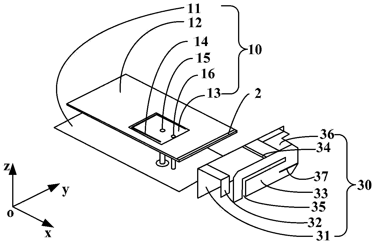
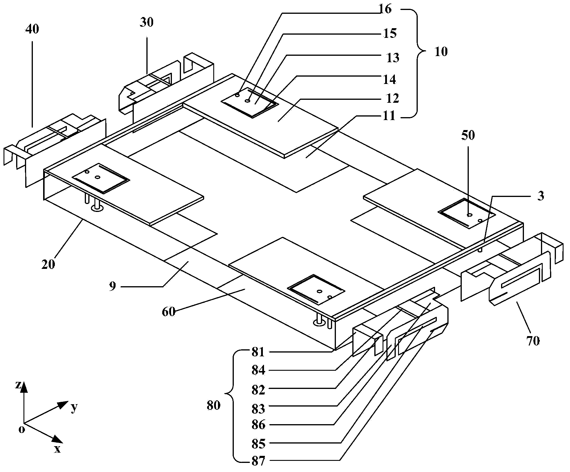
[0039] figure 1 A three-dimensional schematic diagram of a multi-antenna system provided by an embodiment of the present invention. In this embodiment, the multi-antenna system includes: a first-type PIFA10 , a second-type PIFA30 and an isolation stub 2 .

[0040] The first type of PIFA10 is located on the azimuthal plane (eg, figure 1 On the middle xoy coordinate plane), it includes a metal floor 11 , a dielectric board 12 , a radiation...


PUM


Abstract

The invention provides a multiaerial system and a mobile terminal. The multiaerial system comprises a first PIFA (planar inverted-F antenna) (10), a second PIFA (30) and an isolating patch (2). The first PIFA (10) comprises a metal floor (11), a dielectric slab (12), a radiation patch (13), a probe type feed unit (15) and a metal shorting pin (16). The radiation patch (13) is arranged on the upper surface of the dielectric slab (12) and connected with the metal floor (11) through the probe type feed unit (15) and the metal shorting pin (16). The second PIFA (30) is perpendicular to the first PIFA and comprises a metal floor (31), a radiation patch (33), a feed unit (36) and a metal shorting patch (34). The radiation patch (33) is connected with the metal floor (31) through the feed unit (15) and the metal shorting patch (34). The isolating patch (2) is arranged at the edge of one side, close to the second PIFA, of the upper surface of the dielectric slab of the first PIFA. In this way, isolation of the multiaerial system meets the operating requirement of the mobile terminal.

Description

technical field [0001] The present invention relates to antenna technology, in particular to a multi-antenna system and a mobile terminal. Background technique [0002] With the rapid development of mobile communication technology, applications of small mobile terminals such as mobile phones are becoming more and more common. The air interface for the small mobile terminal to communicate with the base station, receive and send radio frequency signals is the antenna, and the power of the small mobile terminal is sent to the base station in the form of electromagnetic waves through the antenna, so the antenna plays a key role in mobile communication technology. [0003] Planar Inverted-F Antenna (Planar Inverted-F Antenna, PIFA) is a commonly used mobile phone antenna. Due to its advantages of small size, light weight, low profile, simple structure and easy integration, it has been more and more widely used in mobile terminals. Applications. [0004] PIFA includes four parts...

Claims


Application Information

Patent Timeline
Patent Type & Authority Applications(China)
IPC IPC(8): H01Q1/52H01Q1/38H01Q5/01H01Q21/00H01Q21/28H01Q1/22
CPCH01Q1/243H01Q9/0421H01Q1/521H01Q21/28H01Q5/364H01Q5/371H01Q1/52H01Q1/38H01Q9/04H01Q21/30
Inventor 翟会清马志慧李振华梁昌洪余荣道刘晟
Owner HUAWEI TECH CO LTD
Why Eureka
Try Eureka