Method for controlling a combustion and/or gasification device

A gasification device and combustion chamber technology, applied in the heat utilization of different solid fuels, the combustion of small-sized solid fuels and/or gasification devices, can solve laborious and expensive problems, achieve simple cost-effectiveness, and optimize air volume Effect

Inactive Publication Date: 2014-12-31
CHRISTOF INT MANAGEMENT
View PDF5 Cites 4 Cited by
  • Summary
  • Abstract
  • Description
  • Claims
  • Application Information

AI Technical Summary

Problems solved by technology

However, using such (infrared) cameras to determine the location of the glowing rim is expensive and laborious

Method used


Image

  • Method for controlling a combustion and/or gasification device

Examples


Embodiment Construction

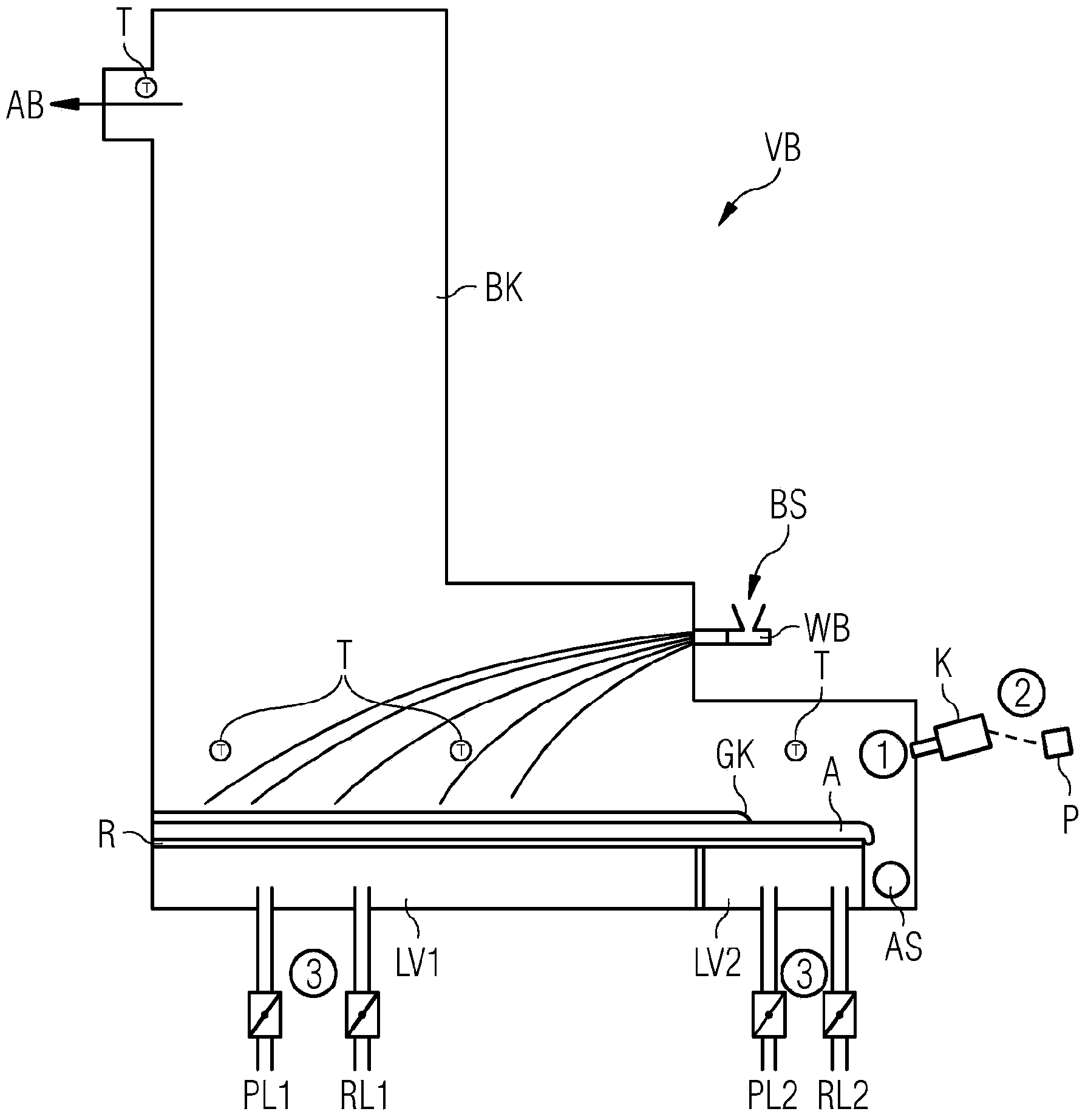
[0022] figure 1 An exemplary combustion or gasification plant VB for small-scale solid fuel BS is schematically shown, said plant VB being arranged for carrying out the method according to the invention. The plant VB comprises at least one combustion chamber BK and a grate R on which the combustion or gasification of the fuel BS is carried out. The fuel BS is injected into the combustion chamber BK for combustion or gasification by means of so-called throw-feeders WB and is thus evenly distributed over the grate R.

[0023] The fuel BS and ash A to be incinerated are located on the grate R which can be subdivided into at least two grate zones arranged in the longitudinal direction of the grate R. Such grate zones are in particular, for example, the so-called combustion or gasification zones, which occupy approximately 4 / 5 of the grate area, and the so-called burnout zones, which comprise approximately 1 / 5 of the grate zone. The combustion or gasification zone of the grate R ...


PUM


Abstract

Combustion and / or gasification devices for the thermal utilisation of different solid fuels, and a method for controlling a combustion and / or gasification device for small-size solid fuels with throw-feeding. A combustion and / or gasification device includes at least one combustion or gasification chamber and a grate with at least two grate zones which are arranged in a longitudinal direction of the grate. A glowing fire edge is formed in one of the grate zones, especially in the so-called burnout zone.

Description

technical field [0001] The present invention generally relates to the field of combustion and / or gasification installations, especially for the utilization of heat from different solid fuels. In particular the invention relates to a method for controlling a combustion and / or gasification plant for small-sized solid fuels by throw-feeding. The combustion and / or gasification device comprises at least one combustion or gasification chamber and a grate having at least two grate zones arranged in the longitudinal direction of the grate (e.g. as the combustion or gasification zone of the first zone and the burnout zone as the second zone). A so-called glowing fire edge is formed in one of the grate zones, especially in the so-called burnout zone. Background technique [0002] Combustion and / or gasification plants for the thermal utilization of various solid fuels are used in industrial fields and / or by local communities, for example for combined heat and power generation. Resid...

Claims


Application Information

Patent Timeline
Patent Type & Authority Applications(China)
IPC IPC(8): F23N5/08F23N3/00F23C9/00F23L1/02F23H1/02
CPCF23H1/02F23L1/02F23C9/00F23N3/00F23G5/50F23C2206/102F23N5/082F23N2021/12F23N2221/12Y02E20/12
Inventor M·哈瑟格鲁伯勒W·马德尔斯皮格
Owner CHRISTOF INT MANAGEMENT
Why Eureka
Try Eureka