

H2S endogenesis cutting-down method and device of quasi aerobic landfill
A technology of endogenous reduction and H2S, which is applied in the field of endogenous reduction of H2S odor, can solve the problems of lack of source control methods and achieve the effect of reducing H2S release
- Summary
- Abstract
- Description
- Claims
- Application Information
AI Technical Summary
Problems solved by technology
Method used
Image

Examples
Embodiment 1
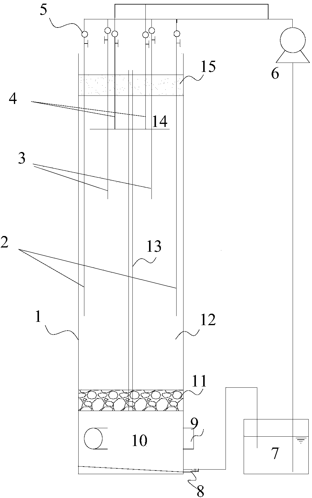
[0064] Such as figure 1 Shown is a schematic structural view of an independent treatment unit (simulated landfill reactor) of the present invention, comprising a reactor shell 1, the reactor shell 1 is an open type, gravel layer 11, garbage layer 12 and fine sand cover The layer 15 is buried in the reactor shell 1 from bottom to top in sequence. Below the gravel layer 11 is the leachate layer 10. The shell of the leachate layer 10 is provided with vents 9, and the number of vents is generally set to 3 to 4. A regulating pool 7 is set near the reactor shell 1, the leachate layer 10 is connected to the regulating pool 7 through the leachate discharge inlet pipe 8, and the inlet of a refill pump 6 is connected to the regulating pool 7.
[0065] The above structural parts can all adopt conventional processing equipment in the field. In this embodiment, the emphasis is on improving the structure of the leachate recharge system. The leachate recharge system includes a vertical rech...
Embodiment 2
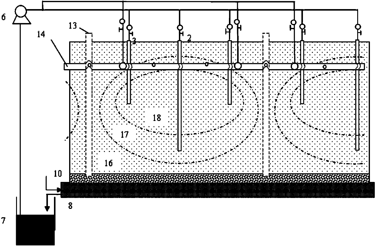
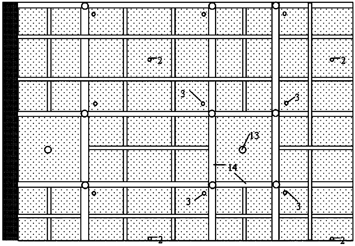
[0094] For large landfills, such as figure 1 Several units shown run in parallel, can be used as will figure 1 The reaction devices shown are used in parallel, and can also be divided into several units in a large landfill, and the setting of the recharge system in each unit is as follows: figure 1 For the recharge system shown in , the recharge systems in all units are controlled in parallel, such as figure 2 with image 3 Shown is the second parallel operation mode.
[0095] The center of each unit is provided with a vertical gas guide pipe 13, and the garbage layer in the unit is divided into an aerobic zone 16, an aerobic zone 17 and an anaerobic zone 18 in turn with the vertical gas guide tube 13 as the center. , the first vertical reinjection well 2 and the second vertical reinjection well 3 are evenly distributed in the garbage layer around the vertical gas guide pipe 13, and all the vertical reinjection wells are distributed on two opposite sides of the unit cro...
PUM
 Abstract
Description
Claims
Application Information