
Intelligent control device and method of underground railway turnout

A technology of intelligent control and turnout, which is applied in the direction of railway signals, railway car body parts, railway signals and safety, etc., can solve the problems of misoperation of turnouts, carelessness, vehicles falling off the road, etc., to improve safety and automation level , Easy to use, simple to install

Active Publication Date: 2015-01-07
ANSTEEL GRP MINING CO LTD
View PDF3 Cites 5 Cited by
  • Summary
  • Abstract
  • Description
  • Claims
  • Application Information

AI Technical Summary

Problems solved by technology

[0002] The existing mine underground turnout control device is that the locomotive driver controls the moving direction of the turnout through the remote controller in his hand according to the actual task requirements. This method has the advantages of simple operation and fast response, but it also has the following disadvantages and safety Hidden dangers: 1. The locomotive driver must be aware of the distribution of all the roadways in the mine. Due to the dim light in the mine, the locomotive often enters the wrong route; 2. The driver needs to drive the locomotive while observing the roadway situation and operate the remote control, which often causes the switch to move 3. The locomotive driver has a heavy workload, and sometimes he does not pay attention to the situation of the front switch due to inattention, which leads to accidents; When two locomotives in a section compete for the control of the same turnout, the remote control signals interfere with each other, which may easily cause serious accidents such as vehicles falling off the road

Method used


Image

  • Intelligent control device and method of underground railway turnout
  • Intelligent control device and method of underground railway turnout
  • Intelligent control device and method of underground railway turnout

Examples


Embodiment Construction

[0024] The present invention will be described in further detail below in conjunction with the accompanying drawings.

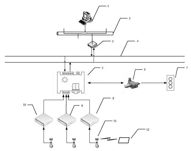
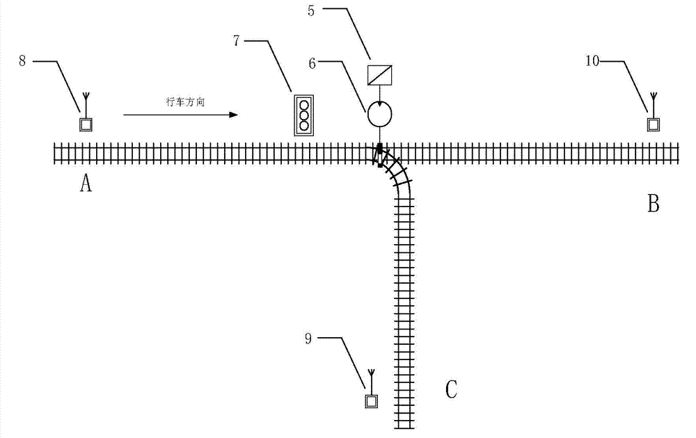
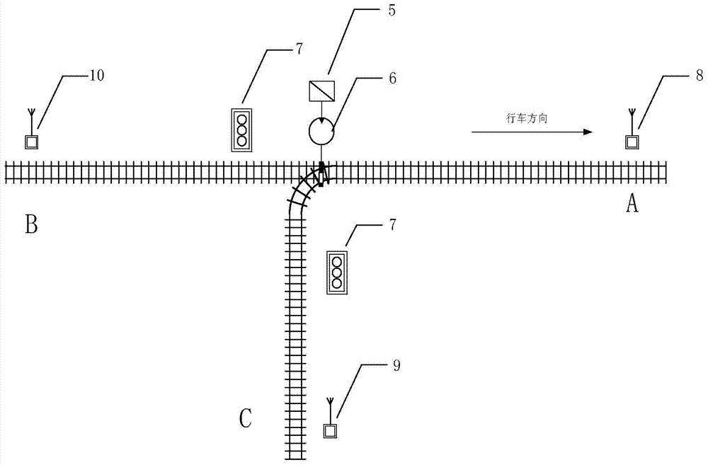
[0025] The block diagram of device structure of the present invention is as figure 1 as shown, figure 1 It is the overall structure diagram of the device system of the present invention, including monitoring and dispatching room host computer 1, Ethernet network 2, CAN bus converter 3, CAN communication network 4, main controller single-chip microcomputer 5, switch machine 6, signal machine 7, card reader Card reader substation 8, card reader substation 9, card reader substation 10, antenna 11, RFID electronic tag 12.

[0026] Among them, the upper computer 1 in the monitoring and dispatching room is an ordinary PC computer, which is connected to the CAN bus converter 3 through the Ethernet 2 . CAN bus converter 3 is a converter from Ethernet to CAN bus network, including one Ethernet, two CAN buses, powered by 12V DC. The main controller single-chip micro...


PUM


Abstract

The invention relates to an intelligent control device of an underground railway turnout and a method thereof. The intelligent control device of the underground railway turnout comprises a main controller single-chip, a CAN switching Ethernet module, a point switch, a signal machine, a card reader substation, a RFID (Radio Frequency Identification) and an antenna, wherein the RFID is placed a locomotive headstock. The control method comprises the following steps: before a locomotive provided with the RFID is driven into a front turnout, and after the locomotive enters an induction range of an inductor mounted in front of the turnout for a certain distance, the inductor automatically identifies locomotive information in the RFID; and according to a preset path and a control mode, the intelligent main controller drives the point switch, transfers the turnout, and provides a signal indication to a driver. The device improves the safety and the automation level of underground mine production of mines, realizes both the automatic control and the remote control function of a dispatcher, records the remote control to automatically change the original planned path, has the advantages of safety, reliability and convenience for use, and needs no participation of the driver or the dispatcher in normal operation.

Description

technical field [0001] The invention belongs to the field of intelligent control, in particular to an intelligent control device and method for railway turnouts under a mine. Background technique [0002] The existing mine underground turnout control device is that the locomotive driver controls the moving direction of the turnout through the remote controller in his hand according to the actual task requirements. This method has the advantages of simple operation and fast response, but it also has the following disadvantages and safety Hidden dangers: 1. The locomotive driver must be aware of the distribution of all the roadways in the mine. Due to the dim light in the mine, the locomotive often enters the wrong route; 2. The driver needs to drive the locomotive while observing the roadway situation and operate the remote control, which often causes the switch to move 3. The locomotive driver has a heavy workload, and sometimes he does not pay attention to the situation of ...

Claims


Application Information

Patent Timeline
IPC IPC(8): B61L7/10E01B23/06
Inventor 刘殿军王激扬田迎春高宪文宫国慧王明顺马东张平陈继宏何杭锋
Owner ANSTEEL GRP MINING CO LTD
Learn More