Grounding wire take-up and pay-off frame

A technology of grounding wires and splitting wires, which is applied in the field of grounding wire retractable racks, can solve problems such as inconvenience in field work, wear and tear of the insulation sheath, and damage to the insulation layer, and achieve the effects of facilitating transportation, protecting the outer insulation layer, and reducing work intensity

Inactive Publication Date: 2015-01-07
STATE GRID CORP OF CHINA +1
View PDF9 Cites 2 Cited by
  • Summary
  • Abstract
  • Description
  • Claims
  • Application Information

AI Technical Summary

Problems solved by technology

The currently used grounding wires are stored, unfolded, and stored in a winding manner. Since the grounding wires are twisted with multiple strands of high-quality soft copper wires, the copper wires are heavy. Ten circles, when the length is long, two people are required to cooperate, which is very inconvenient for on-site work
At the same time, the grounding wire is covered with a soft, high-temperature-resistant transparent insulating sheath to prevent the grounding copper wire from being worn during use. During outdoor construction operations, affected by factors such as the environment and transportation, it is easy to cause abrasion and damage to the insulating sheath. Insulation layer, so there is a greater chance of personal injury, and there is a certain safety risk

Method used


Image

  • Grounding wire take-up and pay-off frame
  • Grounding wire take-up and pay-off frame

Examples


Embodiment

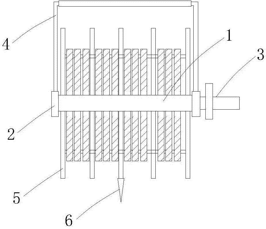
[0015] Example: Combining figure 1 , 2 , The ground wire retractable rack of this embodiment is characterized in that a shaft 1 and a shaft seat 2 at both ends of the shaft 1 are provided. The two ends of the shaft 1 are connected in the shaft seat 2 through bearings, and one end of the shaft 1 is fixedly connected with a drive The crank handle 3 that the shaft 1 rotates; or a shaft sleeve is arranged at both ends of the shaft, and the shaft sleeve is fixedly connected with the handle, and the shaft and the shaft sleeve rotate relatively.

[0016] A handle 4 for lifting the entire retractable rack is provided. In specific settings, the handle can be set in an inverted U shape, and the two free ends of the handle facing downward are fixedly connected to the shaft base 2 respectively.

[0017] On the circumference of the rotating shaft 1, a dividing fence 5 extending radially outward along the rotating shaft is fixed, and a plurality of (can be set to three to six equal) dividing fenc...


PUM


Abstract

The invention discloses a grounding wire take-up and pay-off frame. The grounding wire take-up and pay-off frame is provided with a rotating shaft and shaft bases which are located at two ends of the rotating shaft respectively; each end of the rotating shaft is connected into the corresponding shaft base through a bearing; one end of the rotating shaft is fixedly connected with a crank which is used for driving the rotating shaft to rotate; the grounding wire take-up and pay-off frame is also provided with a lifting handle which is used for lifting the integral take-up and pay-off frame; the lifting handle is in an inverted U shape; two downward free ends of the lifting handle are fixedly connected with the shaft bases respectively; wire separating barriers which extend outward along the radial direction of the rotating shaft are fixedly arranged on the circumference of the rotating shaft; the plurality of wire separating barriers are separately distributed along the axis direction of the rotating shaft in an equally-divided mode; a fixing screw is fixedly arranged at the bottom of the wire separating barrier which is located in the middle of the rotating shaft. According to the grounding wire take-up and pay-off frame, the grounding wire take-up and pay-off can be performed through the crank on the scene and accordingly the labor intensity is reduced.

Description

Technical field: [0001] The invention relates to a grounding wire retracting and releasing rack, in particular to tools and instruments used for retracting, unfolding and storing the grounding wire during line and substation construction and maintenance. Background technique: [0002] The grounding wire is the lifeline to ensure the safe operation of electric power construction personnel on site. In recent years, as the construction and technological transformation of power grid transmission, distribution and transformation projects have increased, especially the operation and maintenance of power grid line equipment has increased day by day, technical measures must be taken to ensure safety when conducting on-site maintenance operations. The item is to ensure the personal safety of maintenance personnel during work by installing grounding lines. As for the grounding wire currently in use, the grounding wire is wound up, unfolded, and stored. Since the grounding wire is twisted ...

Claims


Application Information

Patent Timeline
Patent Type & Authority Applications(China)
IPC IPC(8): B65H75/38B65H75/44
Inventor 钱新王远飞孙伟章义恩钱华龙
Owner STATE GRID CORP OF CHINA
Why Eureka
Try Eureka