Brake micro-motion integrated control system of hydraulic transmission gearbox for forklift

A hydraulic transmission and control system technology, applied in the direction of transmission control, fluid pressure actuation device, components with teeth, etc. To avoid problems such as changes in conditions, to avoid the phenomenon of burning friction plates, humanize the driving performance, and improve the life of the braking system

Active Publication Date: 2016-07-06
ZHEJIANG JINDAO TECH CO LTD
View PDF5 Cites 0 Cited by
  • Summary
  • Abstract
  • Description
  • Claims
  • Application Information

AI Technical Summary

Problems solved by technology

[0002] At present, hydraulic transmission gearboxes for forklifts generally use a hydraulic control circuit combined with electromagnetic reversing valves, buffer valves, micro-movement valves, etc., and cooperate with shift switches and other components to control the shifting process to form a gearbox control system. The control system has the following functions: Several defects: 1. The three-plate combination layout of inching pedal, brake pedal and accelerator pedal is adopted, which increases the complexity of driving operation; 2. The clutch engagement process is fixed and cannot adapt to changes in working conditions. When braking, a large amount of power is consumed on the hydraulic torque converter, which leads to an increase in oil temperature, increased system energy consumption, and reduced life; 3. In many cases, the operator uses the inching pedal as a brake, and often presses the inching pedal for a long time Keeping the gearbox in a semi-linkage overload state for a long time will cause the friction plate to burn and the gearbox to be damaged
The above defects affect the performance and life of the gearbox, reducing its life

Method used


Image

  • Brake micro-motion integrated control system of hydraulic transmission gearbox for forklift
  • Brake micro-motion integrated control system of hydraulic transmission gearbox for forklift
  • Brake micro-motion integrated control system of hydraulic transmission gearbox for forklift

Examples


Embodiment 1

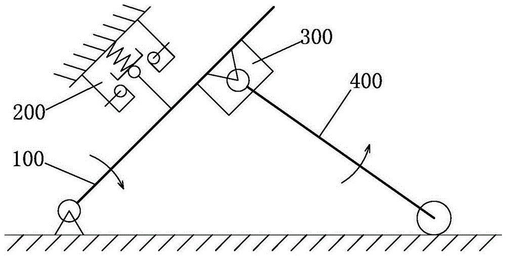
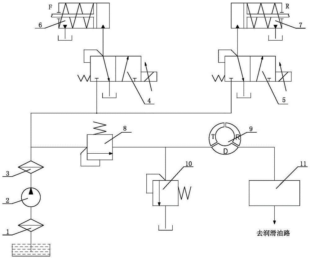
[0024] The brake micro-motion integrated control system of a hydraulic transmission gearbox for a forklift includes a pedal 100 installed on the forklift, a gearbox, an electronic control unit, a proportional hydraulic control system, and a forklift braking system. The pedal 100 is connected to the forklift braking system. Such as figure 1 As shown, the forklift is equipped with a position switch 200 triggered when the pedal 100 is reset upwards and a speed sensor or a displacement sensor 300 that monitors the movement of the pedal 100; figure 2 As shown, the proportional hydraulic control system includes an oil pump 2, a main pressure regulating valve 8, a hydraulic torque converter 9, a relief valve 10 and a cooler 11, and the F clutch 6 in the gearbox passes through the electro-hydraulic proportional reversing valve. It is connected with the output end of the oil pump 2. The R clutch 7 in the gearbox is connected with the output end of the oil pump 2 after passing through ...

Embodiment 2

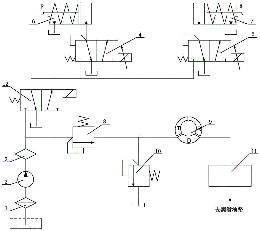
[0029] The brake micro-motion integrated control system of the hydraulic transmission gearbox for forklifts differs from Embodiment 1 only in the proportional hydraulic control system, such as image 3 As shown, the F clutch 6 is connected to the two-position three-way electro-hydraulic proportional reversing valve A4, the R clutch 7 is connected to the two-position three-way electro-hydraulic proportional reversing valve B5, and the electro-hydraulic proportional reversing valve A4 is connected to the electro-hydraulic proportional reversing valve After the valve B5 is connected in parallel, it is connected to the output end of the oil pump 2 through the two-position three-way electromagnetic reversing valve 12; Both the clutch 6 and the R clutch 7 are connected to the oil circuit, they are both in the separated state, there is no power transmission, and the gearbox is in the neutral state; when the electromagnetic reversing valve 12 and the electro-hydraulic proportional reve...

Embodiment 3

[0031] The brake micro-motion integrated control system of the hydraulic transmission gearbox for forklifts differs from Embodiment 1 only in the proportional hydraulic control system, such as Figure 4 As shown, the F clutch 6 is connected to the electromagnetic reversing valve A13, and the R clutch 7 is connected to the electromagnetic reversing valve B14. After the two-position three-way electromagnetic reversing valve A13 and the two-position three-way electromagnetic reversing valve B14 are parallel connected The two-position three-way electro-hydraulic proportional reversing valve 15 is connected to the output end of the oil pump 2; when the electromagnetic reversing valve A13, the electromagnetic reversing valve B14 and the electro-hydraulic proportional reversing valve 15 are not working, both the F clutch 6 and the R clutch 7 The return oil circuit is in a separated state, there is no power transmission, and the gearbox is in the neutral state; when the electro-hydraul...


PUM


Abstract

The invention discloses a braking and micro-motion integrated control system of a hydraulic transmission gearbox for a forklift truck. The braking and micro-motion integrated control system comprises a pedal plate, the gearbox, an electronic control unit and a proportional hydraulic control system; the pedal plate is connected with a forklift truck braking system; the forklift truck is provided with a position switch and a speed sensors or a displacement sensor, wherein the speed sensors or the displacement sensor is used for monitoring the motion condition of the pedal plate; when the position switch is detected to be stepped downward, the forklift truck braking system works and the stepped downward motion speed or motion stroke of the pedal plate is sampled through the electronic control unit; when the stepped downward motion speed or motion stroke of the pedal plate is larger than a set value, the gearbox is controlled by the electronic control unit to be shifted into the neutral gear; when the stepped downward motion speed or motion stroke of the pedal plate is smaller than a set value, the gearbox is controlled by the electronic control unit to be switched between the original gear and the neutral gear. According to the braking and micro-motion integrated control system of the hydraulic transmission gearbox for the forklift truck, the motion condition of the pedal plate is obtained through a braking and micro-motion integrated pedal plate structure and accordingly the driving intention of a driver is determined and the gearbox is controlled to execute the braking and micro-motion work.

Description

technical field [0001] The invention belongs to the field of material handling machinery, and in particular relates to a brake micro-motion integrated control system of a hydraulic transmission gearbox for a forklift. Background technique [0002] At present, hydraulic transmission gearboxes for forklifts generally use a hydraulic control circuit combined with electromagnetic reversing valves, buffer valves, and micro-motion valves, and cooperate with shift switches and other components to control the shifting process to form a gearbox control system. The control system has the following functions: Several defects: 1. The three-plate combination layout of inching pedal, brake pedal and accelerator pedal is adopted, which increases the complexity of driving operation; 2. The clutch engagement process is fixed and cannot adapt to changes in working conditions. When braking, a large amount of power is consumed on the hydraulic torque converter, which leads to an increase in oil...

Claims


Application Information

Patent Timeline
Patent Type & Authority Patents(China)
IPC IPC(8): F16H61/40B66F9/075F15B13/02
CPCB66F9/075F15B13/02F16H61/4008F16H61/4061
Inventor 金刚强王冬剑
Owner ZHEJIANG JINDAO TECH CO LTD
Why Eureka
Try Eureka