
Gas-lubricated bird-wing-shaped groove end face seal structure

A technology of gas lubrication and end face sealing, which is applied in the direction of engine seals, engine components, mechanical equipment, etc., can solve problems such as seal failure, too small opening force, and end face cannot be opened in time, so as to prevent end face wear and reduce end face wear Probability, the effect of improving the opening performance of the end face

Active Publication Date: 2016-05-18
ZHEJIANG UNIV OF TECH
View PDF10 Cites 4 Cited by
  • Summary
  • Abstract
  • Description
  • Claims
  • Application Information

AI Technical Summary

Problems solved by technology

[0003] The invention aims to overcome the problems of the gas-lubricated non-contact mechanical seal in the prior art that the sealing end face wears out when the seal is started, and the seal failure is caused, and the opening force is too small so that the end face cannot be opened in time, and provides a low-speed and low-pressure operating condition with good opening performance and stability. Good, bird-wing-shaped grooved face seal that effectively prevents face wear during start-up and shutdown

Method used


Image

  • Gas-lubricated bird-wing-shaped groove end face seal structure
  • Gas-lubricated bird-wing-shaped groove end face seal structure
  • Gas-lubricated bird-wing-shaped groove end face seal structure

Examples


Embodiment 1

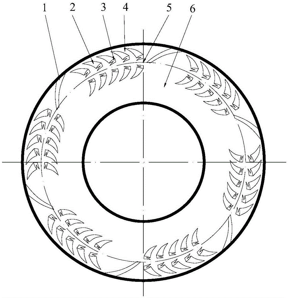
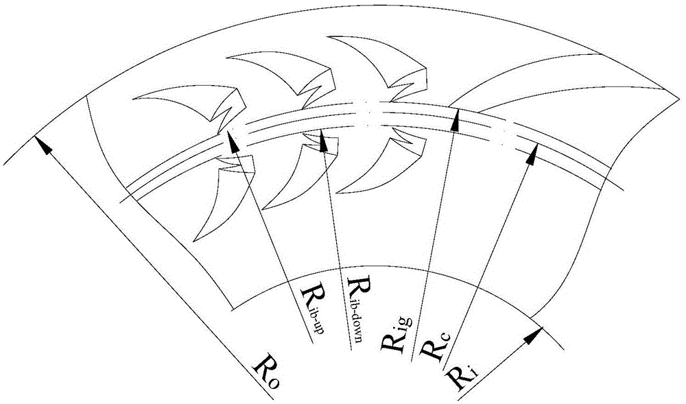
[0027] see figure 1 , 2 , a gas-lubricated imitation bird wing-shaped groove end face seal structure, which includes a moving ring and a static ring for end face sealing, and is characterized in that: at least one of the sealing rings in the moving ring and the static ring is provided with a plurality of imitation bird wings Shaped groove, the imitation bird wing shape groove is made up of imitation tail feather shape groove 3 and imitation flying feather shape groove 2, described tail feather shape groove 3 has the tail part of dovetail shape split, and described imitation The flight feather-shaped groove 2 is roughly in the shape of a cow horn with a thick end and a tail tip, and the described imitation tail feather-shaped groove 3 is arranged horizontally at the thick end of the described imitation flight feather-shaped groove 2, and the described imitation flight feather-shaped groove 2 The thick section of the groove 2 and the thick end of the imitation tail feather shap...

Embodiment 2

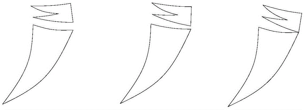
[0039] see image 3 , The difference between this embodiment and Embodiment 1 is that the connection form between the imitation tail feather-shaped groove 3 and the imitation flight feather-shaped groove 2 is one of the following: parallel separation, non-parallel separation, and partial overlap. Other structures and functions are the same as those in Embodiment 1.

Embodiment 3

[0041] see Figure 4 The difference between this embodiment and the first embodiment is that the drainage groove can be one of the following forms: rectangular groove, T-shaped groove, U-shaped groove, and V-shaped groove. Other structures and functions are the same as those in Embodiment 1.


PUM


Abstract

A gas lubrication bird-wing-shape-imitation v groove end face sealing structure comprises two sealing rings with sealed end faces; the two sealing rings comprise a movable ring and a static ring; the end face of at least one of the movable ring and the static ring is provided with a plurality of bird-wing-shape-imitation v grooves; each bird-wing-shape-imitation v groove is composed of a tail-feather-shape-imitation v groove body and a flight-feather-shape-imitation v groove body; the tail-feather-shape-imitation v groove bodies are provided with swallow-tail-shaped furcal tails; the flight-feather-shape-imitation v groove bodies are roughly in a bull horn shape with the thick ends and the tail tip ends; the tail-feather-shape-imitation v groove bodies are transversely arranged at the thick ends of the flight-feather-shape-imitation v groove bodies; the thick segments of the flight-feather-shape-imitation v groove bodies and the thick ends of the tail-feather-shape-imitation v groove bodies are toward airflow; the bird-wing-shape-imitation v grooves are arranged to be bird-wing-shape-imitation v groove annular belts; secondary annular sealing dams are arranged between the bird-wing-shape-imitation v groove annular belts; annular main sealing dams are arranged on the low-pressure sides of the end faces; drainage grooves are arranged on the high-pressure sides of the end faces; the drainage grooves and the bird-wing-shape-imitation v grooves are shallow grooves of the micrometer scale; the depths of the flight-feather-shape-imitation v groove bodies are gradually decreased in the airflow direction. The sealing structure has the advantages of being good in stability and long in service life, and resisting abrasion.

Description

Technical field: [0001] The invention relates to a gas-lubricated end-face mechanical seal structure of a rotary fluid machine, in particular to a gas-lubricated imitation bird-wing-shaped groove end-face seal structure, which is suitable for shafts used for rotating shafts of various compressors, pumps, and kettles. The end sealing device is especially suitable for the shaft end sealing of the gas seal medium with frequent start and stop under medium and low pressure or medium and low speed, and belongs to the technical field of mechanical end face sealing. Background technique: [0002] The known fluid dynamic pressure type groove end face mechanical seal still has some disadvantages, for example: when the non-contact mechanical seal of the groove end face such as spiral groove is in normal operation, the end face groove generates hydrodynamic pressure to increase the opening force of the end face , the increase of the fluid film thickness leads to an increase in the leaka...

Claims


Application Information

Patent Timeline
Patent Type & Authority Patents(China)
IPC IPC(8): F16J15/34
CPCF16J15/406
Inventor 彭旭东江锦波刘鑫白少先陈源李纪云
Owner ZHEJIANG UNIV OF TECH
Learn More