
Gas turbine combustion chamber axial two-stage swirl nozzle

An axial swirl, gas turbine technology, applied in the direction of combustion chamber, continuous combustion chamber, combustion method, etc., can solve the organization and pollutant generation that affect combustion, the limited mixing effect of fuel gas and air, and the mixing of fuel and air. problems such as poor effect, to achieve the effect of improving combustion stability, improving combustion reliability, and reducing impact

Inactive Publication Date: 2015-01-07
BEIJING HUAQING GAS TURBINE & INTEGRATED GASIFICATION COMBINED CYCLE ENG TECH
View PDF6 Cites 2 Cited by
  • Summary
  • Abstract
  • Description
  • Claims
  • Application Information

AI Technical Summary

Problems solved by technology

[0004] However, due to the gap at the bottom of the air swirl blade, the airflow deflection angle on the inner peripheral side of the channel is small, and the swirl strength is weak, resulting in poor mixing effect of fuel and air on this side; at the same time, the axial swirl device has only one stage, The mixing effect of fuel gas and air is limited, which affects the organization of combustion and the generation of pollutants

Method used


Image

  • Gas turbine combustion chamber axial two-stage swirl nozzle
  • Gas turbine combustion chamber axial two-stage swirl nozzle

Examples


Embodiment Construction

[0021] The principle, structure and specific implementation of the present invention will be further described below in conjunction with the accompanying drawings.

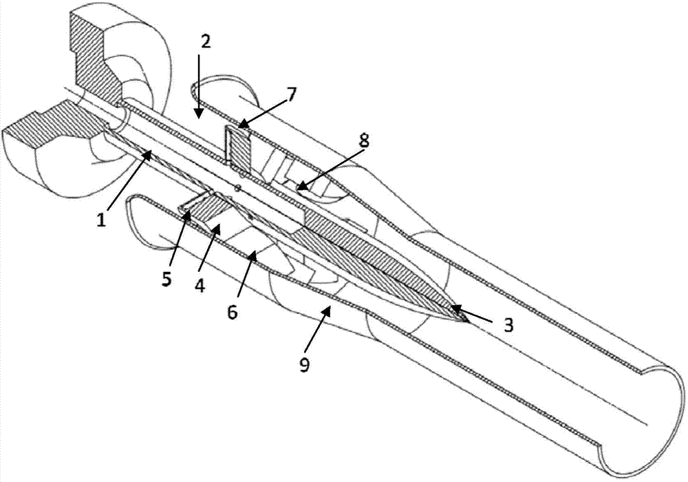
[0022] figure 1 A schematic diagram of the structural principle of a gas turbine combustor axial two-stage swirl nozzle provided by the present invention, the nozzle includes a central fuel channel 1, a peripheral annular air channel coaxially arranged with the central fuel channel 1 and a central cone 3, The peripheral axial annular air passage is arranged with two-stage swirl devices along the axial direction. The first-stage axial swirl device 4 is located at the front end of the peripheral axial annular air passage 2 and is fixed on the central cone 3. A first-stage annular airflow passage 7 is left between the top of the first-stage axial swirl device and the outer wall of the peripheral axial annular air passage 2, and a fuel injection hole 5 is arranged at the front end of the vane of the first-stage axial ...


PUM


Abstract

A gas turbine combustion chamber axial two-stage swirl nozzle is technically characterized in that a two-stage axial swirl device is arranged in the axial direction in a peripheral axial annular air channel. A first-stage swirl device is fixed on a center cone body, and a gap is reserved between the top of the first-stage swirl device and the outer wall face of the nozzle. A second-stage swirl device is arranged on the downstream of the first-stage axial swirl device and fixed on the outer wall face of the annular air channel, and a gap is reserved between the bottom and the center cone body. Two stages of swirl vanes are arranged in a staggering mode. The swirl angle of the second-stage swirl device is larger than that of the first-stage swirl device. The nozzle can ensure the swirl strength on the peripheral side of the inside and the outside of the air channel, the swirl on the inner peripheral side of the air channel is weak in strength, and the axial speed of the air flow can be increased. The swirl on the outer peripheral side of the air channel is high in strength, the combustion area can be controlled reasonably by matching the nozzle outlet speed distribution and the fuel air blending effect, the inner flowing field structure of the combustion chamber is maintained, and combustion stability and good outlet temperature distribution can be ensured.

Description

technical field [0001] The invention relates to a combustion chamber nozzle of a gas turbine, in particular to a structural design of a low-pollution combustion chamber nozzle of a gas turbine using natural gas fuel. Background technique [0002] In my country's current energy structure, thermal power generation using traditional coal-fired technology occupies the vast majority of the share. However, this traditional power generation technology has disadvantages such as low power generation efficiency, high pollutant emissions (especially NOx emissions), and high consumption of fresh water resources. As one of the clean energy technologies, the gas turbine power generation technology fueled by natural gas can effectively reduce pollutant emissions while meeting the power generation load requirements. Among them, the design of the gas turbine combustor nozzle is particularly important for organizing combustion and reducing pollutant emissions . [0003] In the combustion ch...

Claims


Application Information

Patent Timeline
IPC IPC(8): F23R3/38
Inventor 张龙张珊珊查筱晨
Owner BEIJING HUAQING GAS TURBINE & INTEGRATED GASIFICATION COMBINED CYCLE ENG TECH
Learn More