Multi-pipe gas-state fuel mixer using in-pipe mixers

A gaseous fuel and mixer technology, used in gas fuel burners, burners, combustion methods, etc., can solve the problems of incomplete premixed combustion, high local equivalence ratio, uneven temperature distribution, etc. Pipeline time, the effect of reducing pollution emissions

Inactive Publication Date: 2017-06-27
北京智燃天成科技有限公司
View PDF4 Cites 0 Cited by
  • Summary
  • Abstract
  • Description
  • Claims
  • Application Information

AI Technical Summary

Problems solved by technology

However, the currently commonly used natural gas installations are mainly diffusion combustion and incomplete premixed combustion, which have the disadvantages of high local equivalence ratio and uneven temperature distribution, which lead to increased emissions

Method used


Image

  • Multi-pipe gas-state fuel mixer using in-pipe mixers
  • Multi-pipe gas-state fuel mixer using in-pipe mixers
  • Multi-pipe gas-state fuel mixer using in-pipe mixers

Examples


Embodiment Construction

[0033] Embodiments of the technical solutions of the present invention will be described in detail below in conjunction with the accompanying drawings. The following examples are only used to illustrate the technical solutions of the present invention more clearly, and therefore are only examples, rather than limiting the protection scope of the present invention.

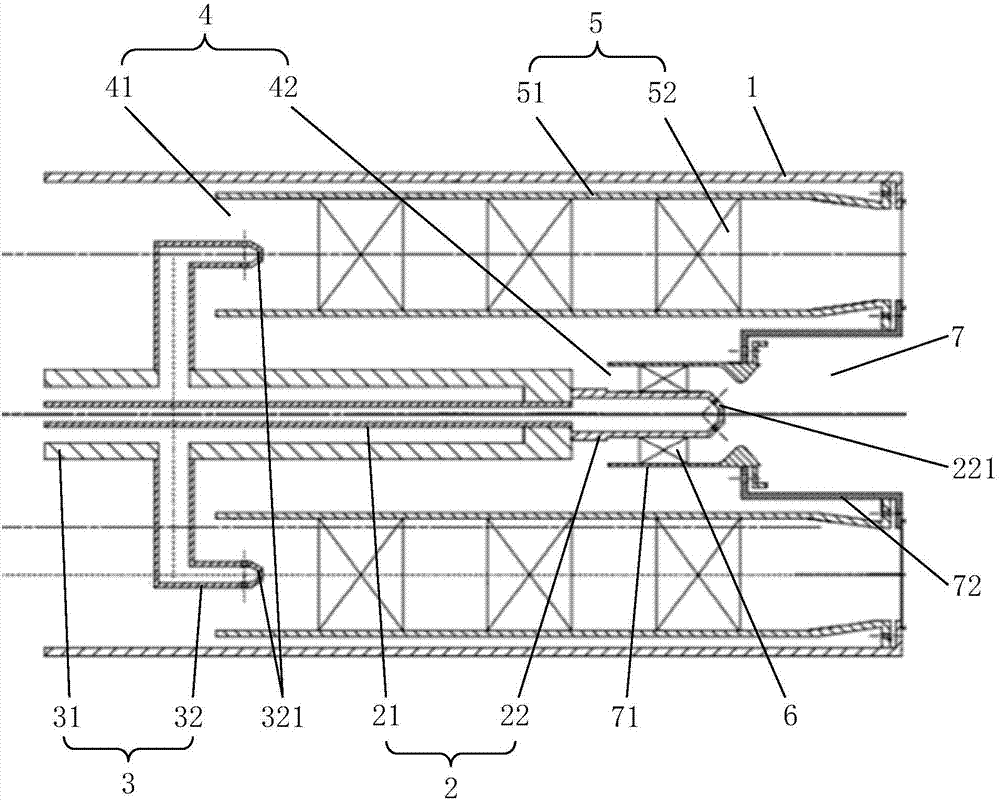
[0034] Such as figure 1 and figure 2 As shown, a multi-tube gaseous fuel blender using an in-tube mixer provided by an embodiment of the present invention includes a tubular casing 1, and a central fuel channel 2, a peripheral The fuel passage 3 and the annular air passage 4, wherein the peripheral fuel passage 3 is sleeved on the outer periphery of the central fuel passage 2, the central fuel passage 2 includes a central fuel delivery pipe 21 arranged along the central axis of the housing, and is connected to the central fuel delivery pipe 21. The central fuel nozzle 22 at the end of the pipe 21, and the centra...


PUM


Abstract

The invention provides a multi-pipe gas-state fuel mixer using in-pipe mixers. The multi-pipe gas-state fuel mixer comprises a shell; a center fuel channel, a peripheral fuel channel and an annular air channel are coaxially formed in the shell in the radial direction; the peripheral fuel channel comprises a peripheral fuel conveying pipe, and multiple peripheral fuel nozzles peripherally arranged and connected to the outer wall of the peripheral fuel conveying pipe; the annular air channel comprises a peripheral air channel and a center air channel; a peripheral cyclone device and a center cyclone device are respectively arranged in the peripheral air channel and the center air channel; the peripheral cyclone device comprises multiple pipes uniformly distributed in the peripheral direction; and multiple in-pipe mixers are axially distributed in the pipes. Through a multi-pipe premixing mode of the peripheral channel and application of the in-pipe mixers, the oil-gas mixing is uniform, and the pollution emission is reduced.

Description

technical field [0001] The invention relates to a gas mixing device, in particular to a multi-tube gaseous fuel blender using an in-tube mixer. Background technique [0002] With the development of society, people have higher and higher requirements for efficient use of energy and environmental protection. However, conventional fossil fuels still occupy a considerable proportion, and the carbon dioxide and pollutant emissions they produce have caused great environmental pressure. Therefore, people advocate energy conservation and emission reduction. On the one hand, new energy sources such as solar energy and wind energy are developed to reduce carbon emissions; On the one hand, it is hoped that the fuel utilization of fossil fuels can be more efficient and the pollution emissions will be lower. However, new energy sources such as solar energy and wind energy are not suitable for large-scale promotion due to their natural characteristics and current technical limitations. ...

Claims


Application Information

Patent Timeline
Patent Type & Authority Applications(China)
IPC IPC(8): F23D14/62
CPCF23D14/62F23D2203/007
Inventor 林宇震张弛王建臣王晓峰
Owner 北京智燃天成科技有限公司
Why Eureka
Try Eureka