
A kind of LED flip chip and its manufacturing method

A manufacturing method and flip-chip technology, applied in the direction of electrical components, circuits, semiconductor devices, etc., to achieve the effects of improving brightness, white light brightness, and increasing the probability of emission

Active Publication Date: 2017-06-16
XIANGNENG HUALEI OPTOELECTRONICS
View PDF8 Cites 0 Cited by
  • Summary
  • Abstract
  • Description
  • Claims
  • Application Information

AI Technical Summary

Problems solved by technology

However, there is still room for improvement in the light extraction efficiency of the current flip-chip light extracted from the sapphire substrate.

Method used


Image

  • A kind of LED flip chip and its manufacturing method
  • A kind of LED flip chip and its manufacturing method

Examples


Embodiment Construction

[0035] Certain terms are used, for example, in the description and claims to refer to particular components. Those skilled in the art should understand that hardware manufacturers may use different terms to refer to the same component. The specification and claims do not use the difference in name as a way to distinguish components, but use the difference in function of components as a criterion for distinguishing. As mentioned throughout the specification and claims, "comprising" is an open term, so it should be interpreted as "including but not limited to". "Approximately" means that within an acceptable error range, those skilled in the art can solve the technical problem within a certain error range and basically achieve the technical effect. The subsequent description of the specification is a preferred implementation mode for implementing the application, but the description is for the purpose of illustrating the general principle of the application, and is not intended...


PUM

PropertyMeasurementUnit
thermal conductivityaaaaaaaaaa
thicknessaaaaaaaaaa
thicknessaaaaaaaaaa

Abstract

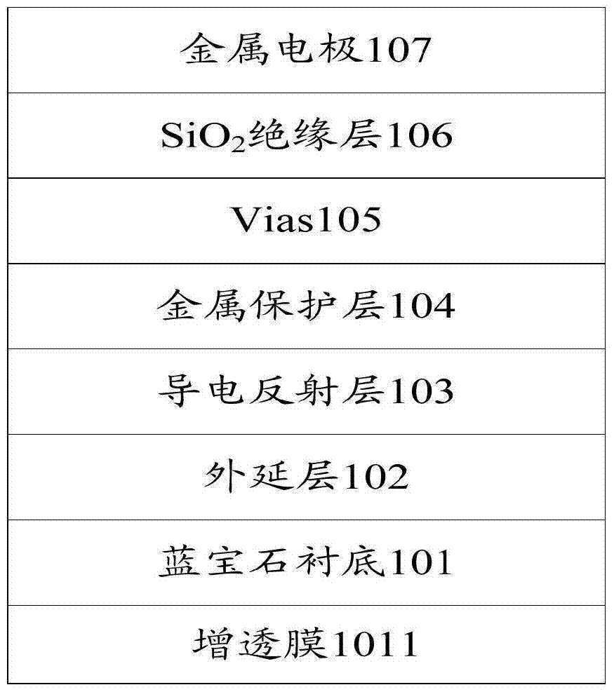
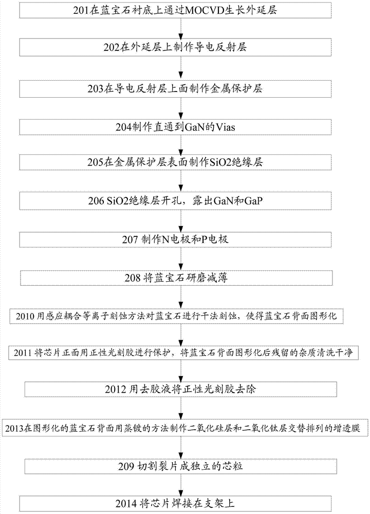
The invention discloses an LED flip chip. The LED flip chip sequentially comprises a sapphire substrate, an epitaxial layer, a conductive reflecting layer, a metal protective layer, a Vias and SiO2 insulating layer and metal electrodes from bottom to top, wherein the sapphire substrate is a sapphire substrate, obtained after inductive coupling plasma etching, with a graphical back side, an antireflection film is further arranged on the back side of the sapphire substrate, the antireflection film is an antireflection film, manufactured with an evaporation method, with silicon dioxide layers and titanium dioxide layers alternately arranged, the sum of the number of the silicon dioxide layers in the antireflection film and the number of the titanium dioxide layers in the antireflection film ranges from 6 to 15, and the thickness of the silicon dioxide layers in the antireflection film and the thickness of the titanium dioxide layers in the antireflection film range from 20 nm to 300 nm. The invention further provides a manufacturing method of the LED flip chip. The emitting angle of light at the bottom of the LED flip chip is increased through a graphical sapphire substrate technology, the light outgoing probability is increased, brightness is improved, and the brightness of white light is improved by 1% to 7%.

Description

technical field [0001] The present application relates to the technical field of chip manufacturing, and more specifically, to an LED flip chip and a manufacturing method thereof. Background technique [0002] At present, the LED industry is developing in the direction of high brightness and high light efficiency. In the early front-mounted chips, the light extraction efficiency of the chip was reduced because the P electrode and the current diffusion layer composed of Ni / Au would absorb part of the light. Although the current front-mounted chip introduces a reflective electrode and an ITO transparent conductive layer, the reflective electrode composed of metal cannot completely reflect the light, and some light will still be absorbed, and the ITO transparent conductive layer is not completely transparent. Some light is absorbed. Therefore, about 25% of the light absorbed by the reflective electrode and ITO in the current front-mounted chip is about 25%. In addition, the ...

Claims


Application Information

Patent Timeline
Patent Type & Authority Patents(China)
IPC IPC(8): H01L33/10H01L33/58H01L33/60H01L33/00
CPCH01L33/10H01L33/58H01L33/60H01L2933/0058
Inventor 胡弃疾苗振林汪延明
Owner XIANGNENG HUALEI OPTOELECTRONICS
Learn More