Air conditioning device for vehicle

A technology for air conditioners and vehicles, which can be used in vehicle components, transportation and packaging, air handling equipment, etc., and can solve problems such as insufficient heating capacity

Inactive Publication Date: 2015-01-07
JAPAN CLIMATE SYSTEMS CORP +1
View PDF10 Cites 19 Cited by
  • Summary
  • Abstract
  • Description
  • Claims
  • Application Information

AI Technical Summary

Problems solved by technology

[0008] In the heating operation mode, especially when the outdoor air temperature is low, stronger heating is required, and it can be considered that if the upstream indoor heat exchanger The role of the heater will lead to insufficient heating capacity

Method used


Image

  • Air conditioning device for vehicle
  • Air conditioning device for vehicle
  • Air conditioning device for vehicle

Examples


no. 1 approach

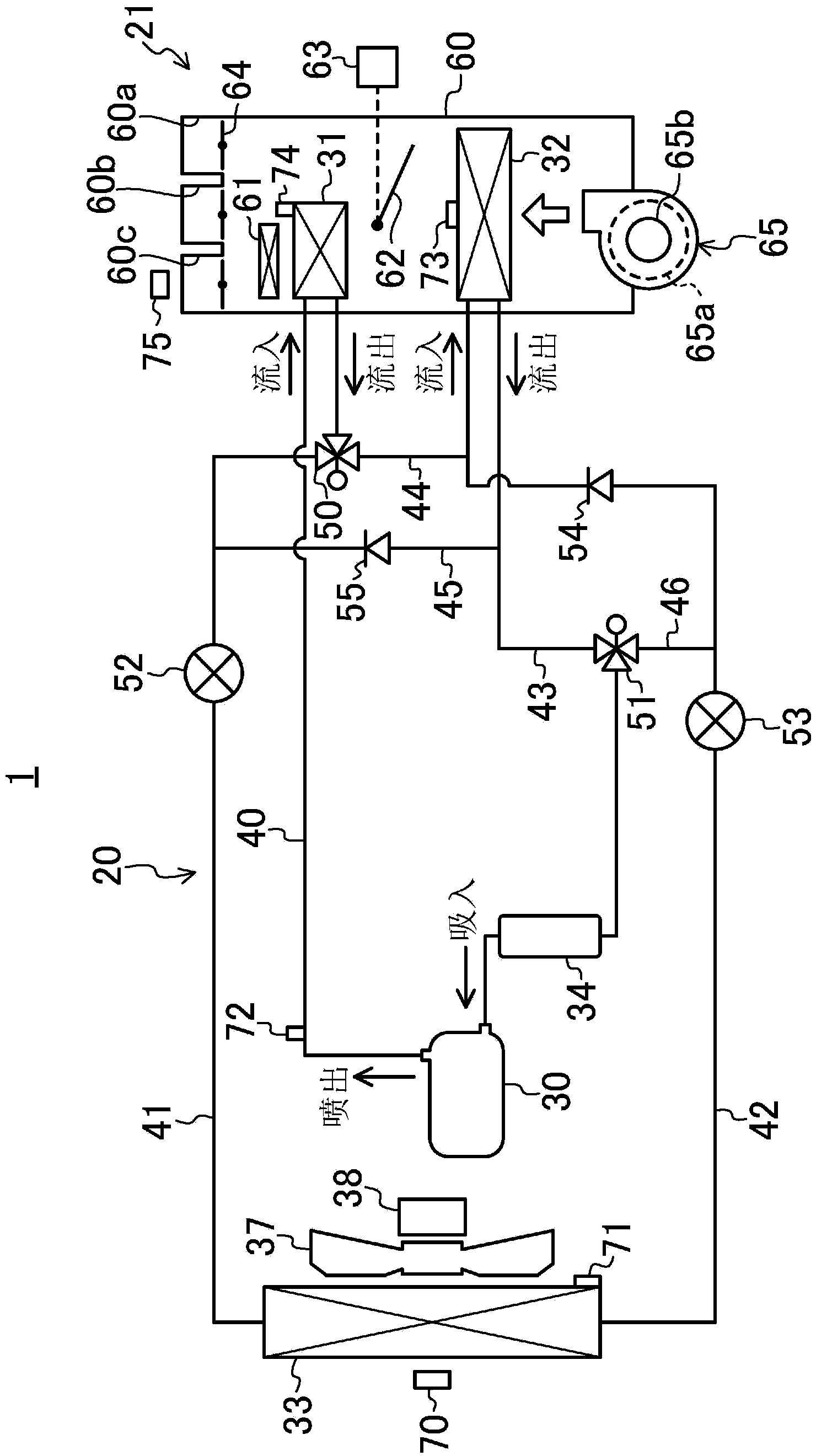
[0113] figure 1 It is a schematic configuration diagram of the vehicle air conditioner 1 according to the first embodiment of the present invention (embodiments of the first to third inventions). A vehicle in which the vehicle air conditioner 1 is installed is an electric vehicle having a driving battery and a driving electric motor.

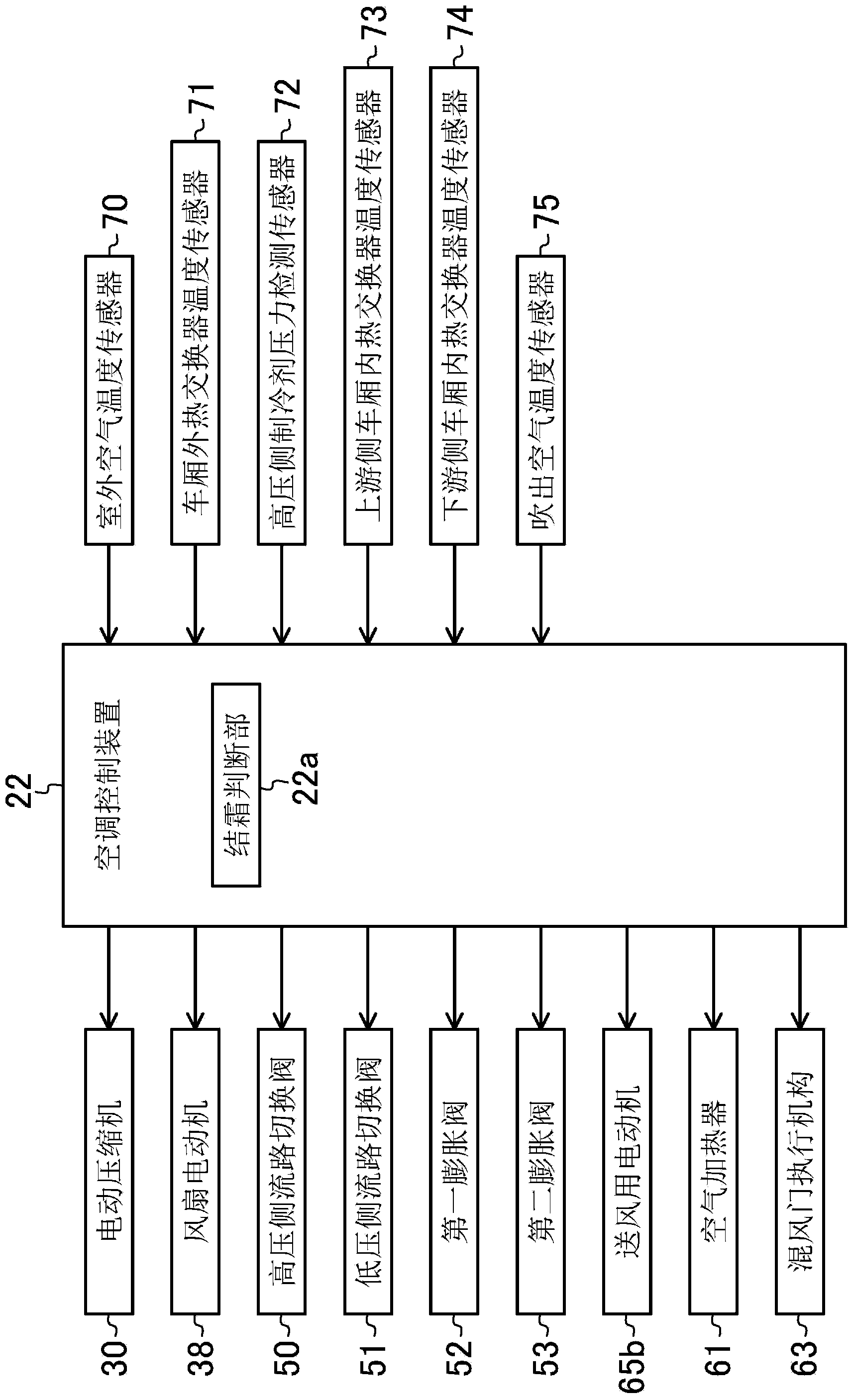
[0114] The vehicle air conditioner 1 includes: a heat pump device 20, an air conditioner unit 21 in the vehicle compartment, and an air conditioner control device 22 for controlling the heat pump device 20 and the air conditioner unit 21 in the vehicle compartment (in figure 2 shown in ).

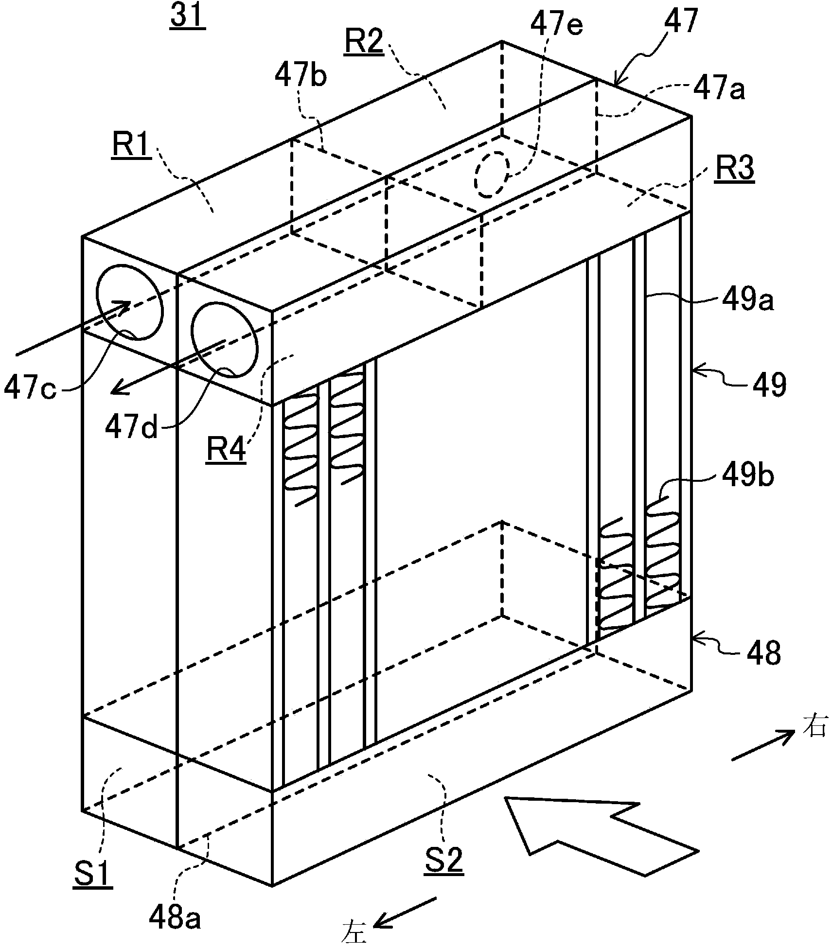
[0115] The heat pump device 20 includes an electric compressor 30 for compressing refrigerant, a downstream side indoor heat exchanger (first indoor heat exchanger) 31 installed in the vehicle cabin, and an air flow direction of the downstream side indoor heat exchanger 31 installed in the vehicle cabin. The upstream indoor heat exchanger (second indoor he...

no. 2 approach

[0229] Figure 13 It is a schematic configuration diagram of the vehicle air conditioner 1 according to the second embodiment of the present invention (embodiments of the fourth and fifth inventions). Hereinafter, the same symbols are assigned to the same parts as those of the first embodiment, and their descriptions are omitted, and the parts different from those of the first embodiment will be described in detail.

[0230] The pipe indicated by the symbol 45 in the second embodiment is the first branch refrigerant pipe 45 . The first branch refrigerant pipe 45 is branched from the main refrigerant pipe 41 and connected to the main refrigerant pipe 43 . The second branch refrigerant pipe 46 is branched from the main refrigerant pipe 42 and connected to the main refrigerant pipe 43 .

[0231] In the second embodiment, the pipe indicated by reference numeral 44 is the pipe 44 dedicated to high-temperature refrigerant. The high-temperature refrigerant dedicated pipe 44 branch...

no. 3 approach

[0248] Figure 19 It is a schematic configuration diagram of the vehicle air conditioner 1 according to the third embodiment of the present invention (embodiments of the sixth to eighth inventions). Hereinafter, the same symbols are assigned to the same parts as those of the first embodiment, and their descriptions are omitted, and the parts different from those of the first embodiment will be described in detail.

[0249] The pipe indicated by the symbol 45 in the third embodiment is the first branch refrigerant pipe 45 . The first branch refrigerant pipe 45 is branched from the main refrigerant pipe 41 and connected to the main refrigerant pipe 43 . The second branch refrigerant pipe 46 branches from a portion of the main refrigerant pipe 42 closer to the exterior heat exchanger 33 than the low-temperature refrigerant dedicated pipe 42 a , and is connected to the main refrigerant pipe 43 .

[0250] In the third embodiment, the pipe indicated by reference numeral 44 is a hi...


PUM


Abstract

A heat pump device 20 includes an air conditioning control device 22 configured to switch the heat pump device 20 among a plurality of operation modes including an air-heating operation mode in which an indoor heat exchanger 32 serves as a radiator and an outdoor heat exchanger 33 serves as a heat absorber, and an air-cooling operation mode in which the indoor heat exchanger 32 serves as a heat absorber and the outdoor heat exchanger 33 serves as a radiator. The air conditioning control device 22 switch a refrigerant pipe such that refrigerant is, in the air-cooling operation mode, supplied to part of the outdoor heat exchanger 33 serving as a refrigerant inlet in the air-heating operation mode.

Description

technical field [0001] The present invention relates to a vehicle air conditioner mounted on a vehicle. Background technique [0002] Heretofore, air conditioners including heat pump devices have been known as air conditioners mounted on, for example, hybrid vehicles, electric vehicles, and the like. The vehicle heat pump device described above is constituted by sequentially connecting an electric compressor, an external heat exchanger installed outside the vehicle cabin, an expansion valve, and an indoor heat exchanger installed inside the vehicle cabin through refrigerant piping (see, for example, Patent Document 1 ). [0003] When the heat pump device is in the heating operation mode, the refrigerant is flowed so that the interior heat exchanger functions as a radiator and the exterior heat exchanger functions as a heat sink, and when the heat pump device is in the cooling operation mode, The refrigerant is allowed to flow so that the interior heat exchanger acts as a h...

Claims


Application Information

Patent Timeline
Patent Type & Authority Applications(China)
IPC IPC(8): B60H1/22B60H1/32F25B6/04
CPCB60H1/00907B60H1/321B60H1/3213F25B6/04B60H1/22B60H2001/00942B60H1/32B60H1/00321B60H2001/2271B60H1/323B60H1/00921F25B41/20F25B5/04F25B47/022F25B2313/0315F25B2347/023F25B2700/11B60H2001/00961F25B41/39
Inventor 滨本浩深渡瀬康平大竹庆彦小森晃松元昂若野胜喜
Owner JAPAN CLIMATE SYSTEMS CORP
Why Eureka
Try Eureka