Stirring and defoaming device

A stirring defoaming and stirring chamber technology, which is applied in the direction of liquid degassing, transportation and packaging, mixers, etc., can solve the problems of stable current value, narrow dynamic range, easy to produce errors, etc., to achieve set time suppression, easy High-speed rotation to achieve the effect of working efficiency

Inactive Publication Date: 2015-01-14
SUGINO MACHINE
View PDF3 Cites 9 Cited by
  • Summary
  • Abstract
  • Description
  • Claims
  • Application Information

AI Technical Summary

Problems solved by technology

[0011] However, in the device described in Patent Document 1, since the drive motor for rotation is arranged in the container holder, it is difficult to stabilize the current value required for the rotation of the drive motor for rotation due to the revolution of the drive motor for rotation itself. The problem is that errors are likely to occur when various controls are performed, corresponding to the fact that the drive motor for rotation and the drive motor for revolution are arranged at separate positions.
Therefore, the dynamic range of control is narrowed, and the heat generation is large, making it difficult to stably control the number of revolutions of the autorotation

Method used


Image

  • Stirring and defoaming device
  • Stirring and defoaming device
  • Stirring and defoaming device

Examples


Embodiment Construction

[0062] Hereinafter, specific embodiments to which the present invention is applied will be described in detail with reference to the drawings.

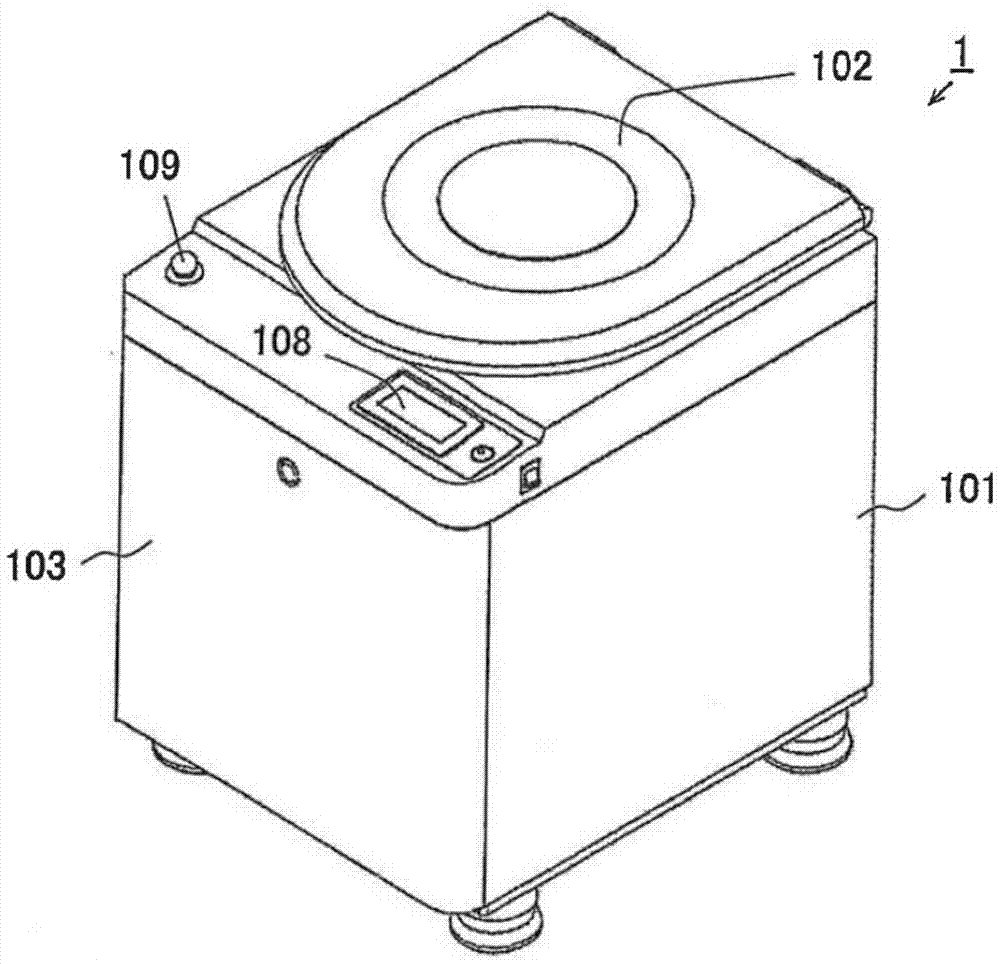
[0063] figure 1 It is a perspective view which shows the stirring degassing apparatus 1 to which the embodiment of this invention was applied. The stirring and degassing apparatus 1 of this embodiment has a cover 102 on the upper portion of a substantially cubic box 101 , and a control panel 108 and an emergency stop button 109 are arranged on the front side of the upper surface.

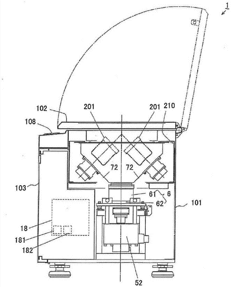
[0064] figure 2 It is a perspective view of main parts viewed from the side side of the stirring and degassing apparatus 1 of the present embodiment. In the stirring and degassing apparatus 1 of this embodiment, two raw material storage containers 201 are arranged in a rotationally symmetrical manner, and the shape above the base 6 serves as a stirring chamber 210 for storing the raw material storage containers 201 . Furthermore, a control circuit 18 is...


PUM


Abstract

The present invention provides a stirring and defoaming device, and the rotation of the device can be controlled at a high accuracy. Meanwhile, the stirring and defoaming operation is conducted at a high reproducibility. The stirring and defoaming device comprises a container support used for holding a material receiving container; a self-rotation drive shaft coupled to the container support through a first coupling mechanism; a revolution drive shaft configured at the outer peripheral side of the self-rotation drive shaft, coupled to the self-rotation drive shaft through a second coupling mechanism and coupled to the container support through a third coupling mechanism; a base arranged at the outer peripheral side of the revolution drive shaft and coupled to the revolution drive shaft through a fourth coupling mechanism; a driven motor used for driving the self-rotation of the material receiving container; a driving motor used for driving the revolution of the revolution drive shaft; and a control device used for controlling the motors. The driven motor and the driving motor are fixed onto the base, and are of an independent structure respectively.

Description

technical field [0001] The invention relates to a stirring defoaming device. Background technique [0002] Dental materials, pharmaceutical materials, cosmetic substrates, color materials such as inks, paints, and pigments, synthetic resins such as silicones, epoxy resins, and polyurethanes, adhesives, and other chemical materials in the form of liquids, gels, and pastes When using chemical materials composed of raw materials or a mixture of multiple raw materials, in order to achieve homogenization, it is required to defoam while stirring. Therefore, there is an increasing demand for agitation degassing devices capable of simultaneously handling agitation and degassing. [0003] In this specification, the following treatment is defined as agitation degassing treatment: a treatment including either one or both of agitation and degassing using a stirring degassing apparatus capable of simultaneously performing stirring and degassing. [0004] Conventionally, a stirring and ...

Claims


Application Information

Patent Timeline
Patent Type & Authority Applications(China)
IPC IPC(8): B01D19/00B01F29/90
CPCB29B7/106B29B7/845
Inventor 藤田志朗杉森正
Owner SUGINO MACHINE
Why Eureka
Try Eureka