Infrared Gas Sensor

A gas sensor, infrared technology, applied in the field of sensors, can solve the problems of optical cavity design limitations and other problems, and achieve the effect of simple structure, small shape and long optical path

Active Publication Date: 2017-03-01
HENAN HANWEI ELECTRONICS
View PDF8 Cites 1 Cited by
  • Summary
  • Abstract
  • Description
  • Claims
  • Application Information

AI Technical Summary

Problems solved by technology

[0003] Common infrared light sources and detectors are mostly cylindrical. The infrared light source and detector need to be combined with the optical cavity to form a complete optical path, and the pins of the infrared light source and detector need to be soldered on the circuit board. This situation has caused The design of the optical cavity is limited to the welding method of the infrared light source, detector and circuit board

Method used


Image

  • Infrared Gas Sensor
  • Infrared Gas Sensor
  • Infrared Gas Sensor

Examples


Embodiment Construction

[0021] The technical solution of the present invention will be described in detail below in conjunction with the accompanying drawings.

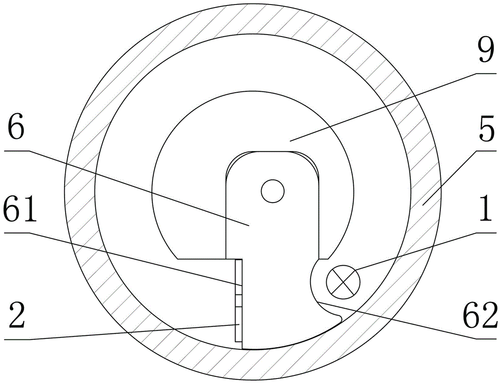
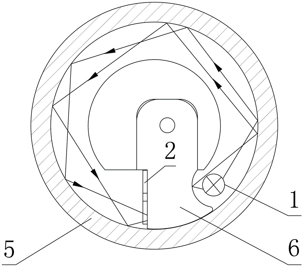
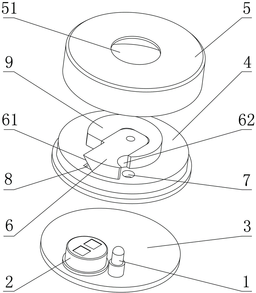
[0022] Such as figure 1 and figure 2 As shown, an infrared gas sensor includes an optical cavity, a signal acquisition circuit board 3 and an infrared light source 1 and a detector 2 respectively connected to the signal acquisition circuit board, and the cavity wall of the optical cavity is provided with A light source installation hole 7 and a detector installation hole 8 , the infrared light source 1 is installed in the light source installation hole 7 , and the detector 2 is installed in the detector installation hole 8 . The light source installation hole 7 and the detector installation hole 8 are provided on the cavity wall of the optical cavity, and the infrared light source 1 and the detector 2 are respectively connected to the signal acquisition circuit board 3, which greatly facilitates The assembly of the infrared light source 1...


PUM

PropertyMeasurementUnit
reflectanceaaaaaaaaaa

Abstract

The invention provides an infrared gas sensor. The infrared gas sensor comprises an optical cavity, a signal collection circuit board and an infrared light source and a detector, wherein the infrared light source and the detector are respectively connected with the signal collection circuit board; a light source mounting hole and a detector mounting hole are formed in the cavity wall of the optical cavity; the infrared light source is mounted in the light source mounting hole; the detector is mounted in the detector mounting hole; the inner wall of the optical cavity, the cylindrical reflection surface of a reflection column, the light source reflection surface of an optical reflection lock and the receiving reflection surface form a C-shaped light path of the infrared gas sensor. The infrared gas sensor has the advantages of being simple in structure, convenient to assemble, small in size and long in light path.

Description

technical field [0001] The invention belongs to the technical field of sensors, and in particular relates to an infrared gas sensor. Background technique [0002] The infrared gas sensor uses the principle of non-dispersive infrared (NDIR) to detect the target gas existing in the air. Infrared gas sensors usually consist of four parts: infrared light source, optical cavity, detector, signal acquisition and processing circuit. The usual infrared gas sensor uses an infrared light source to emit infrared spectrum at one end of the optical cavity, and the detector receives the optical structure of the infrared spectrum at the other end of the optical cavity. After the infrared spectrum is emitted, it is absorbed by the target gas in the optical cavity and passed through the optical sensor. After multiple reflections on the inner wall of the cavity, it converges on the detector, and the information of the target gas is obtained by analyzing the spectral signal received by the de...

Claims


Application Information

Patent Timeline
Patent Type & Authority Patents(China)
IPC IPC(8): G01N21/3504
Inventor 王书潜杨清永冯山虎
Owner HENAN HANWEI ELECTRONICS
Why Eureka
Try Eureka