
Multifunctional X-ray channel type CT/DR detection device

A detection equipment, X-ray technology, applied in the field of X-ray channel CT/DR multi-functional detection equipment, can solve the problems of low precision, narrow application range, inability to take into account efficiency and precision, etc., to improve production, accurate image research and judgment, Effects of Improving Scanning Work Efficiency

Active Publication Date: 2015-01-14
XIAMEN BOFENG ELECTRONICS TECH
View PDF6 Cites 11 Cited by
  • Summary
  • Abstract
  • Description
  • Claims
  • Application Information

AI Technical Summary

Problems solved by technology

[0006] The equipment has a single function and can only be used for planar scanning (DR) or tomographic scanning (CT), which cannot balance efficiency and precision, because CT has high precision but low detection efficiency; DR has high efficiency but low precision
[0007] Basically, it is customized by industry (or according to the workpiece). Generally, it can only meet the quality inspection and judgment of specific products or specific industries. The scope of application is relatively narrow, and it cannot adapt to changes in the specifications, shapes, materials (density) and other factors of the workpiece. Due to this limitation , if a new process is introduced or a new workpiece is detected, new equipment needs to be purchased separately, and the procurement and manufacturing costs, management and maintenance costs will all increase accordingly, and the cost of site and space will also increase
[0008] DR or CT imaging share a set of motion mechanism, random inspection or full inspection, different requirements for efficiency and accuracy, and functional conversion cannot be taken into account

Method used


Image

  • Multifunctional X-ray channel type CT/DR detection device
  • Multifunctional X-ray channel type CT/DR detection device
  • Multifunctional X-ray channel type CT/DR detection device

Examples


Embodiment Construction

[0022] The present invention will be further described in detail below in conjunction with the drawings and specific embodiments.

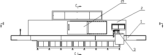
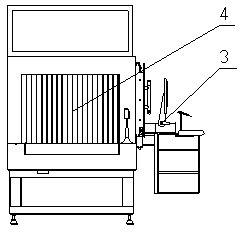
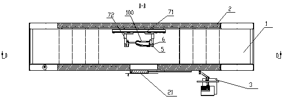
[0023] Such as Figure 1-5 As shown, the embodiment of the present invention includes a detection conveyor line 1, a lead protection channel 2, a lead protection door 21, an on-site operation table 3, a lead curtain 4, a CT scanning mechanism 8, an X-ray machine 91, a linear array detector 92, and workpiece installation The workpiece mounting seat preferably includes a lateral movement mechanism 71, a telescopic mechanism 72, a lifting mechanism 73, a chuck 5, and a chuck rotation driving mechanism 6.

[0024] Specifically, the detection conveyor line 1 is used for conveying the workpiece 100, which is basically in-line structure, and can be formed by a motor-driven roller and a roller-driven conveyor belt wound on it.

[0025] The lead protection channel 2 is arranged above the detection conveyor line 1 to shield radiation and prevent radiation from esc...


PUM


Abstract

The invention discloses a multifunctional X-ray channel type CT / DR detection device. The multifunctional X-ray channel type CT / DR detection device comprises a detection transmission line, a lead protection channel covering the detection transmission line, a lead protection door arranged on one side of the lead protection channel, a lead curtain suspended on two ends of the lead protection channel, an X-ray machine arranged at the top of the inner part of the lead protection channel, a linear array detector corresponding to the top and the bottom of the X-ray machine and arranged at the bottom of the inner part of the lead protection channel, a workpiece mounting base arranged inside the lead protection channel, in front-back correspondence to the lead protection door and used for mounting, moving and rotating the workpieces, a CT scanning mechanism arranged on the workpiece mounting base and a field operation table connected with the X-ray machine, the workpiece mounting base and the CT scanning mechanism and used for controlling the workpieces to scan, image and move. According to the multifunctional X-ray channel type CT / DR detection device, a DR moving mechanism and a CT moving mechanism capable of independently running are respectively mounted inside the detection device and are capable of respectively running according to the requirement, so that DR and CT functions can transform and make an organic combination.

Description

[0001] Technical field [0002] The present invention relates to the technical field of non-destructive testing (non-destructive testing, non-destructive testing), quality testing and research and judgment equipment, and in particular to an X-ray channel type CT / DR (CT: Computed Tomography, DR: Digital Radiography, Digital X-ray photography) multifunctional testing equipment. [0003] Background technique [0004] At present, the main structure and principle of the technology (equipment) used for non-destructive inspection of products are: transilluminate the workpiece through the X-ray device, convert it into a digital signal by the imaging system, and then restore it to an image file by computer software, and then conduct quality research and judgment. , Marking, storage and other operations. [0005] Practice shows that the existing such equipment has obvious problems and shortcomings: [0006] The equipment has a single function, which can only be used for planar scan (DR) or tom...

Claims


Application Information

Patent Timeline
Patent Type & Authority Applications(China)
IPC IPC(8): G01N23/04
Inventor 李顺仁周广涛
Owner XIAMEN BOFENG ELECTRONICS TECH
Learn More