
Motor dynamic load simulation system

A dynamic load and simulation system technology, applied in the direction of motor generator testing, etc., can solve problems that cannot be quantified, difficult to calculate, and cannot accurately control the current value of the hysteresis clutch, achieving the effect of improving reliability and accuracy

Active Publication Date: 2015-01-14
GD MIDEA AIR-CONDITIONING EQUIP CO LTD
View PDF17 Cites 11 Cited by
  • Summary
  • Abstract
  • Description
  • Claims
  • Application Information

AI Technical Summary

Problems solved by technology

[0004] The following disadvantages exist in the prior art: the torque is transmitted to the motor to be tested by adding the motor under test and the hysteresis clutch for joint control, which is too complicated to operate, and the torque transmitted by the combination of the motor under test and the hysteresis clutch is not sufficient. easy to calculate and not quantifiable
In addition, the technology of controlling the hysteresis clutch or brake does not point out the specific implementation method of adjusting the current. It can be artificially added a voltage regulating device to adjust the current, which does not conform to the actual conversion of the relationship between current and torque, and cannot be accurately controlled. The current value of the hysteresis clutch, so it is impossible to truly simulate the effect of the preset dynamic load torque value on the motor rotor

Method used


Image

  • Motor dynamic load simulation system
  • Motor dynamic load simulation system
  • Motor dynamic load simulation system

Examples


Embodiment Construction

[0026] Embodiments of the present invention are described in detail below, examples of which are shown in the drawings, wherein the same or similar reference numerals designate the same or similar elements or elements having the same or similar functions throughout. The embodiments described below by referring to the figures are exemplary only for explaining the present invention and should not be construed as limiting the present invention.

[0027] The following disclosure provides many different embodiments or examples for implementing different structures of the present invention. To simplify the disclosure of the present invention, components and arrangements of specific examples are described below. Of course, they are only examples and are not intended to limit the invention. Furthermore, the present invention may repeat reference numerals and / or letters in different instances. This repetition is for the purpose of simplicity and clarity and does not in itself indicat...


PUM


Abstract

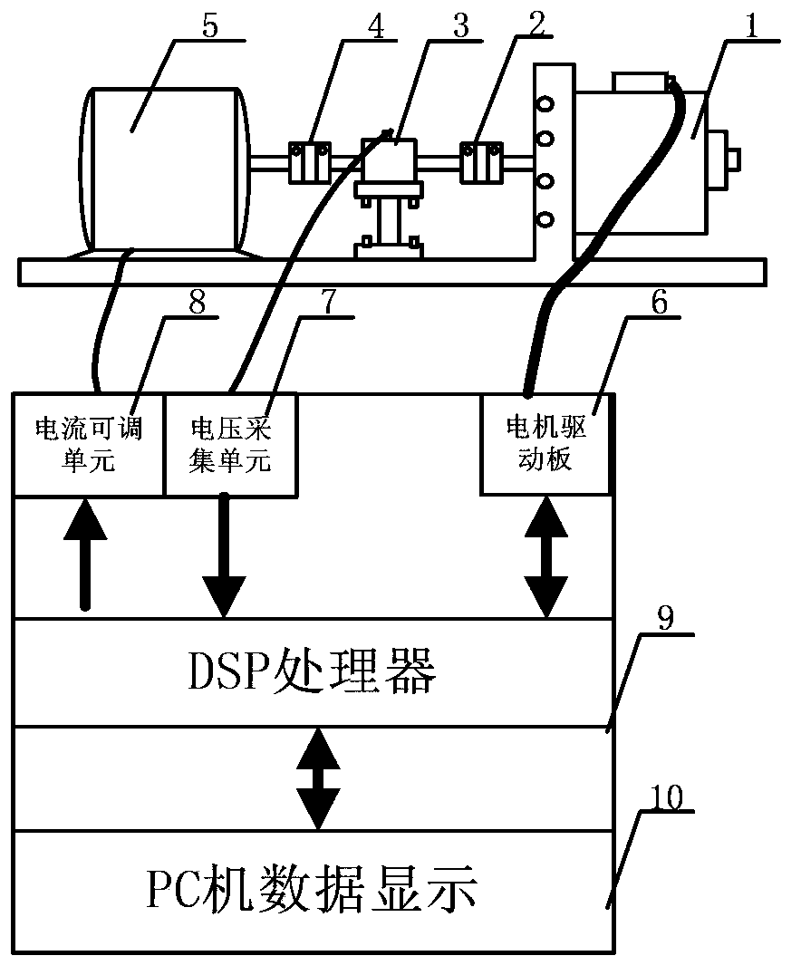
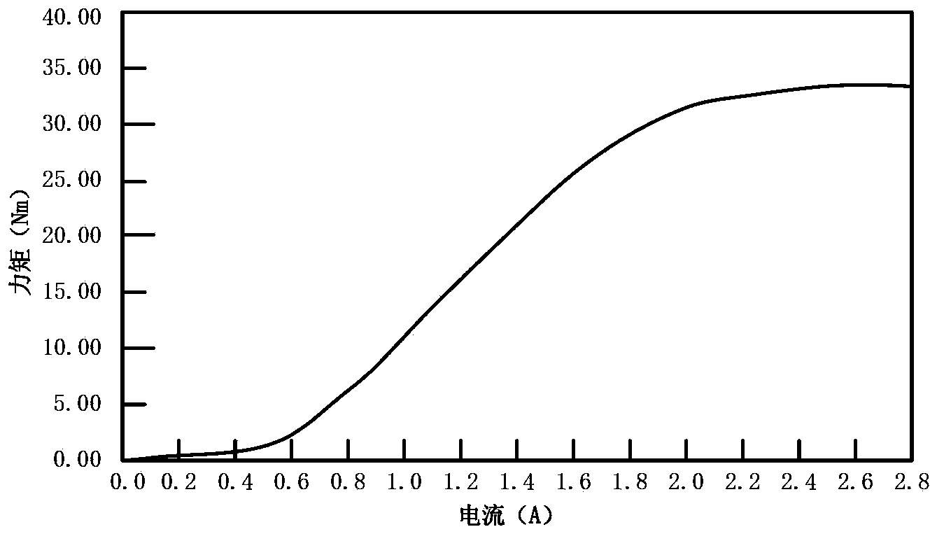
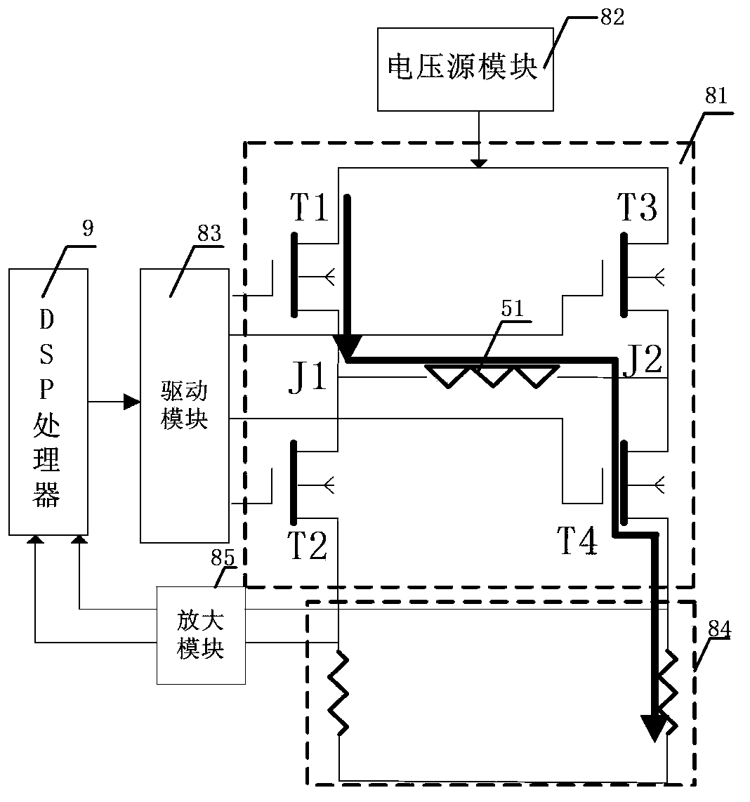
The invention discloses a motor dynamic load simulation system. The motor dynamic load simulation system comprises a motor, a first coupler, a torque detector, a second coupler, a magnetic remanence brake, a drive, a collector, a current regulator and a controller, wherein the motor is provided with an output rotary shaft, the collector is connected with the torque detector, the current regulator is connected with the magnetic remanence brake, the output torque of the magnetic remanence brake is regulated through the current regulator, the controller is connected with the drive, the collector and the current regulator, and the controller has control over the motor through the drive, obtains a current regulation value corresponding to the target torque according to the torque, obtained by the collector, of the output rotary shaft and a preset current-torque characteristic curve, and has control over the current regulator according to the current regulation value so that the magnetic remanence brake can output the target torque. The motor dynamic load simulation system can accurately simulate the motor dynamic load, so that the real time performance, the reliability and the accuracy of the motor dynamic load simulation system are improved.

Description

technical field [0001] The invention relates to the technical field of motor dynamic simulation, in particular to a motor dynamic load simulation system. Background technique [0002] In motor testing, the dynamic application of the load on the motor is directly related to the research method of simulating the motor control. In the field of air-conditioning compressors, the load of the motor changes dynamically during the actual operation process, and the dynamic load makes it difficult to simulate the motor effectively. [0003] In an existing typical motor load simulation method, the torque change curve is set in the controller, and a corresponding control current is generated to the clutch. When the motor under test rotates, the torque is transmitted to the motor under test through the clutch, so that The load torque change of the motor under test is jointly determined by the torque produced by the motor under test and the current of the clutch change. [0004] The foll...

Claims


Application Information

Patent Timeline
IPC IPC(8): G01R31/34
Inventor 熊毅
Owner GD MIDEA AIR-CONDITIONING EQUIP CO LTD
Learn More