
Probe block and detector

A probe block and connecting line technology, applied in the field of detection and display, can solve the problems of long maintenance time, difficult inspection, and long time consumption, so as to improve the utilization rate, reduce the risk of burnout, and reduce the effect of burnout.

Inactive Publication Date: 2015-01-14
HEFEI XINSHENG OPTOELECTRONICS TECH CO LTD +1
View PDF6 Cites 5 Cited by
  • Summary
  • Abstract
  • Description
  • Claims
  • Application Information

AI Technical Summary

Problems solved by technology

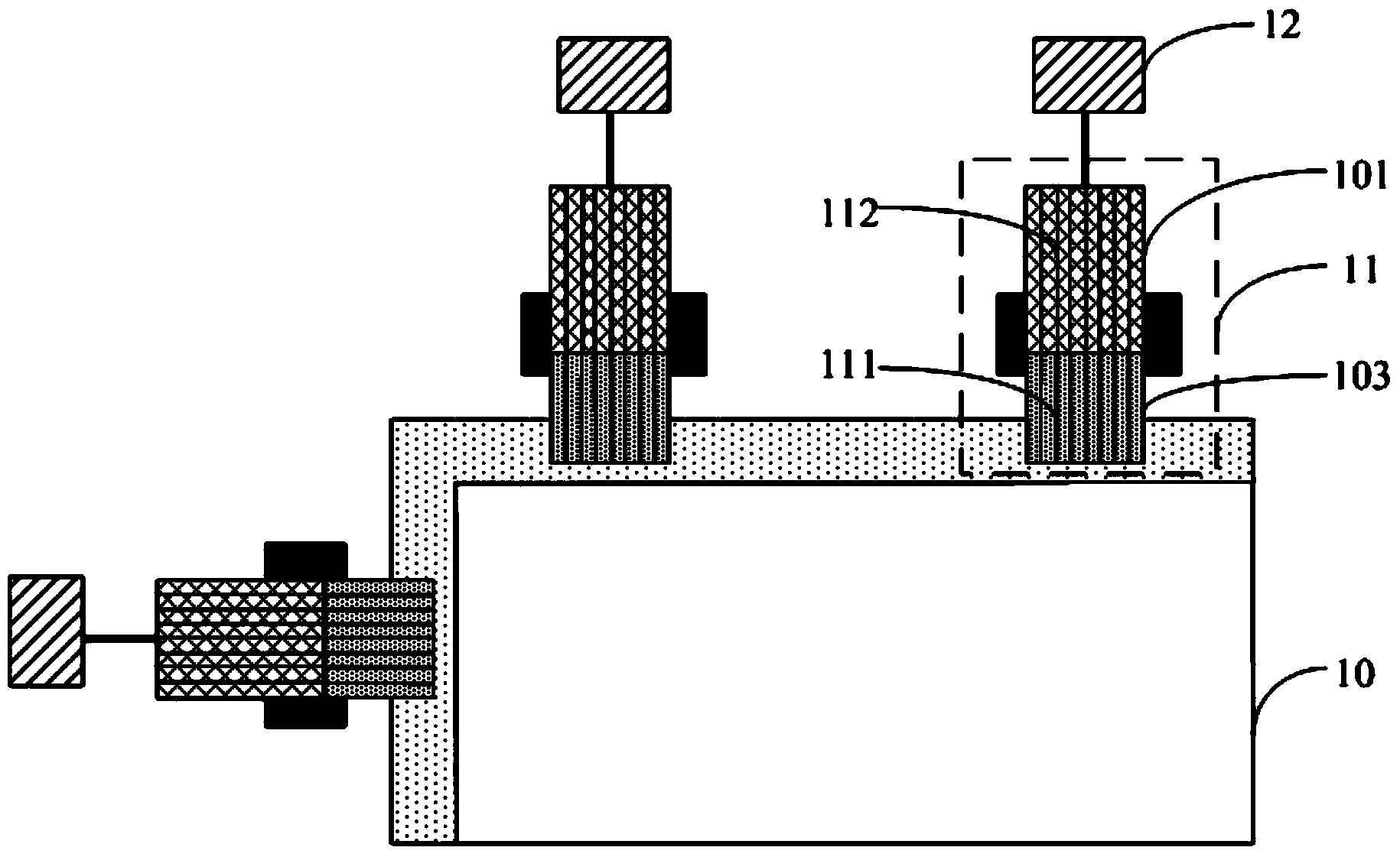
Since the alignment of the lines in the COF 103 and the lines in the bonding pad of the liquid crystal panel cannot be guaranteed to be 100% accurate, there are a few cases where alignment deviations occur, resulting in short circuits. The voltage of some signals is strong, and the voltage input to the COF 103 is also strong. If there is a short circuit in the line at this time, it will cause the COF 103 to burn out.
After the COF is burned, the LCD panel will display abnormally when it is lit. It is difficult to troubleshoot this phenomenon, and it takes a long time to adjust it. In addition, it is difficult to repair the probe block with the COF burnt out. The maintenance time of the probe block is long and the maintenance cost is high.
[0004] To sum up, in the prior art, the probe blocks are easy to be burned when performing lighting inspection on the liquid crystal panel, and the repair of the burnt probe blocks is difficult, the maintenance time is long, and the maintenance cost is high.

Method used


Image

  • Probe block and detector
  • Probe block and detector
  • Probe block and detector

Examples


Embodiment Construction

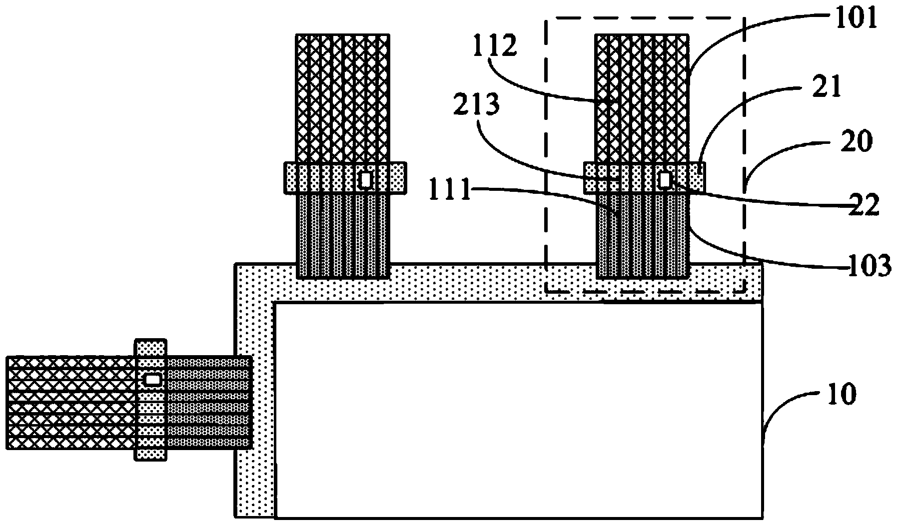
[0027] Embodiments of the present invention provide a probe block and a detection device, which are used to reduce the risk of burning the probe block and improve the utilization rate of the probe block.

[0028] The probe blocks provided by specific embodiments of the present invention will be described in detail below with reference to the accompanying drawings.

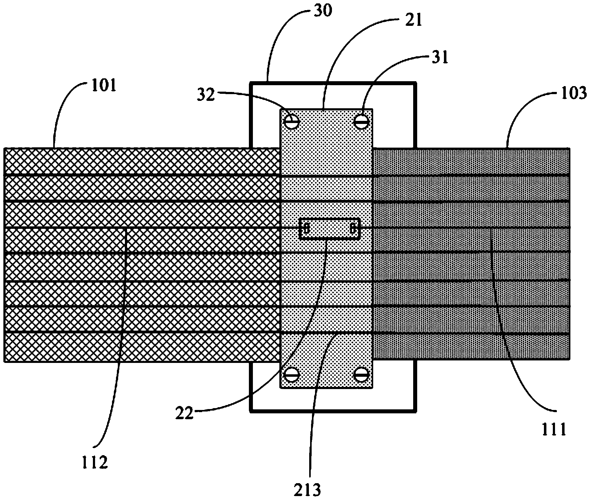
[0029] Such as figure 2 As shown, the specific embodiment of the present invention provides a probe block 20, including: COF 103 and FPC 101, COF 103 includes a number of first connecting wires 111 that overlap with the lines in the liquid crystal panel bonding pad, and FPC 101 includes A number of second connection lines 112 connected to the lines in the signal generator, the probe block 20 also includes a connector 21, wherein,

[0030] The connector 21 includes a number of third connecting wires 213 correspondingly connected to a first connecting wire 111 and a second connecting wire 112, at least one third co...


PUM


Abstract

The invention discloses a probe block and a detector. The detector is used for reducing burning risk of the probe block, and utilization rate of the probe block is increased. The probe block comprises a chip on film and a flexible circuit, the chip on film comprises a plurality of first connecting wires overlapped with circuits in a liquid crystal panel welding plate, and the flexible circuit comprises a plurality of second connecting wires connected with circuits in a signal generator. The probe block further comprises a connector, the connector comprises a plurality of third connecting wires correspondingly connected with one first connecting wire and one second connecting wire, at least one of the third connecting wire is provided with an anti-overload current device arranged on the third connecting wires with high-level input, and the anti-overload current device is used for reducing high level or directly disconnecting the third connecting wires.

Description

technical field [0001] The invention relates to the technical fields of display and detection, in particular to a probe block and a detection device. Background technique [0002] In the manufacturing process of liquid crystal panels, the box-forming process is to bond the finished color filter glass and array glass, and obtain a liquid crystal panel of a specific size after cutting. In order to reduce costs, most manufacturers choose to stick polarizing film after boxing Before lighting the panel, it can detect whether there are bad spots on the LCD panel, such as bright spots or dark spots. [0003] During the lighting inspection, at first the liquid crystal panel 10 is fixed on the inspection base, such as figure 1 As shown, the chip on film (Chip On Film, COF) 103 in the probe block 11 is overlapped with the bonding pad (not shown) of the liquid crystal panel 10, so that the signal lines in the chip on film and the lines of the liquid crystal panel Connection, wherein,...

Claims


Application Information

Patent Timeline
Patent Type & Authority Applications(China)
IPC IPC(8): G02F1/13G01R1/067
CPCG02F1/1309G01R1/07307
Inventor 徐靖李世军朱奎志盛化鹏
Owner HEFEI XINSHENG OPTOELECTRONICS TECH CO LTD
Learn More