Mask plate

A technology of mask plate and shading area, which is applied in the field of mask plate, can solve problems such as increase of black matrix area, decrease of light transmittance, and decrease of black matrix aperture ratio, and achieve the goal of increasing aperture ratio and reducing shading area Effect

Inactive Publication Date: 2015-01-14
BOE TECH GRP CO LTD +1
View PDF6 Cites 18 Cited by
  • Summary
  • Abstract
  • Description
  • Claims
  • Application Information

AI Technical Summary

Problems solved by technology

It can be seen that the diffraction and scattering of light causes the area of ​​the actually formed black matrix to increase, which in turn leads to a decrease in the aperture ratio of the black matrix and a decrease in light transmittance.

Method used


Image

  • Mask plate
  • Mask plate
  • Mask plate

Examples


Embodiment 1

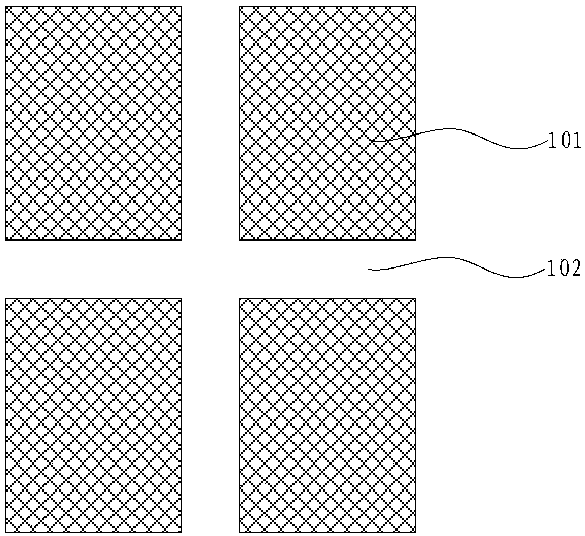
[0026] This embodiment provides a mask, including a plurality of rectangular light-shielding areas arranged in an array, the gaps between the plurality of rectangular light-shielding areas form a light leakage area, and the light leakage area includes a plurality of horizontal light leakage strips and vertical light leakage strip. An auxiliary light-shielding area is also provided on the mask plate, and the auxiliary light-shielding area blocks the light incident on the corner of the rectangular light-shielding area, so that the light intensity of the light at the corner of the rectangular light-shielding area is distributed at right angles.

[0027] In this embodiment, by adding an auxiliary light-shielding area to the structure of the original mask plate, the auxiliary light-shielding area blocks the light that hits the corner of the rectangular light-shielding area of ​​the mask plate, so that the light intensity of the light at the corner of the light-shielding area is at a...

Embodiment 2

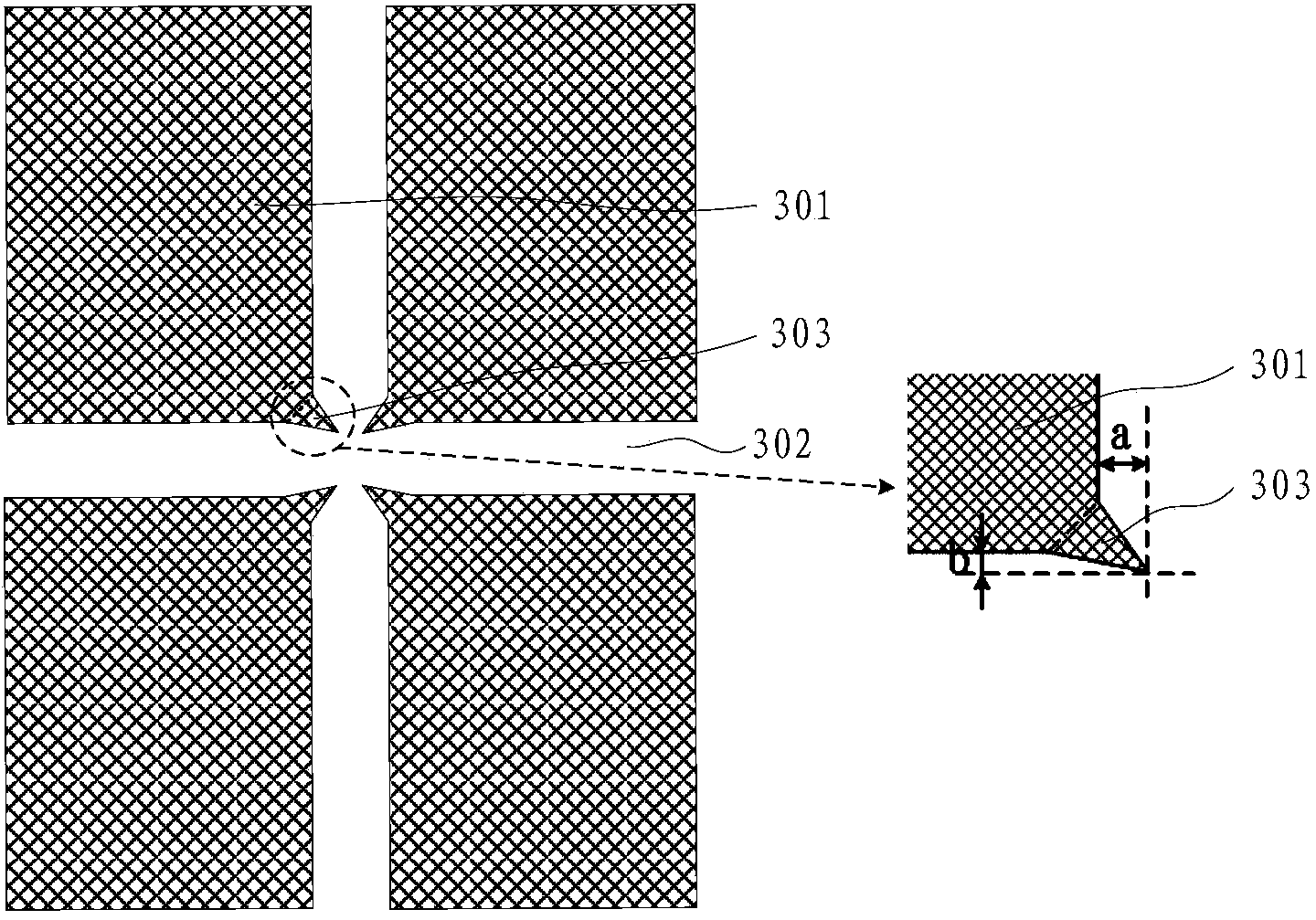
[0029] Based on Embodiment 1, this embodiment provides a mask plate, such as image 3 As shown, the mask plate includes: a plurality of rectangular light-shielding regions 301 arranged in an array, and the gaps between the plurality of rectangular light-shielding regions 301 form a light leakage region 302, and the light leakage region includes a plurality of horizontal light leakage strips criss-crossing and longitudinal Leakage strip: the auxiliary light-shielding area 303 is located at the corner of the rectangular light-shielding area 301 and is joined to the rectangular light-shielding area 301, and the auxiliary light-shielding area 303 is wedge-shaped, and the wedge angle of the wedge is an acute angle, and the wedge angle points to the light leakage area 302.

[0030] It should be noted that, in this embodiment, the specific shape of the rectangular light-shielding area 301 may be a rectangle with notched corners, so as to be connected with the auxiliary light-shielding...

Embodiment 3

[0040] Based on Embodiment 1, this embodiment provides a mask plate, such as Figure 4 As shown, the mask includes: a light leakage region 402 , a rectangular light shielding region 401 and an auxiliary light shielding region 403 . Wherein, the auxiliary light-shielding area 403 is located at the corner of the rectangular light-shielding area 401, and is spaced from the rectangular light-shielding area 401, and the auxiliary light-shielding area 403 includes two light-shielding strips intersecting to form an included angle, and the angle formed by the intersection of these two light-shielding strips is The opening faces the corner of the rectangular light-shielding area 401 .

[0041] When the above-mentioned mask is used for exposure, the light will be diffracted and scattered at the angle formed by the intersection of the corner of the rectangular light-shielding area 401 and the two light-shielding strips of the auxiliary light-shielding area 403, and the two diffraction an...


PUM

PropertyMeasurementUnit
widthaaaaaaaaaa
angleaaaaaaaaaa

Abstract

The invention provides a mask plate which comprises a plurality of rectangular shading regions which are arranged in an array, wherein clearances between the multiple rectangular shading regions form light leakage regions; the light leakage regions comprise a plurality of transverse light leakage strips and longitudinal light leakage strips which are staggered transversely and longitudinally; an auxiliary shading region is also arranged on the mask plate and can shade light rays at corners of the rectangular shading regions, so that the light intensities of the light rays at the corners of the rectangular shading regions are in right-angle distribution. According to the mask plate with the structure, the light intensity distribution of the shading regions at the corners of the light leakage regions is of a right angle or is close to the right angle, so that the mask plate can form a black matrix with right-angle corners; therefore, the shading areas of the corner regions of the black matrix are reduced, the aperture opening ratio of the black matrix is increased, and the aim of increasing the light ray transmittance rate of a display panel is achieved.

Description

technical field [0001] The invention relates to the field of display technology, in particular to a mask plate. Background technique [0002] With the continuous development of display technology, people have higher and higher requirements on the display brightness of the display panel, how to increase the aperture ratio of the color filter, and then increase the light transmittance of the display panel is becoming more and more important. [0003] The color filter mainly includes: a black matrix and a coloring layer, wherein the black matrix has a grid structure, and the coloring layer generally includes red, green and blue photoresists, and these photoresists are located in the black matrix grid. In the prior art, a patterning process is usually used to form a black matrix. The specific process is: covering the black matrix material on the substrate, covering the black matrix material with a photoresist layer, and then using a mask plate with a black matrix pattern to cove...

Claims


Application Information

Patent Timeline
Patent Type & Authority Applications(China)
IPC IPC(8): G03F1/38
CPCG03F1/38
Inventor 汪栋吴洪江
Owner BOE TECH GRP CO LTD
Why Eureka
Try Eureka