
Semiconductor device and manufacturing method thereof

A semiconductor and device technology, applied in semiconductor/solid-state device manufacturing, semiconductor devices, electric solid-state devices, etc., can solve problems such as collapse, inability to effectively control threshold voltage, and difficulty in implementing FinFETs

Active Publication Date: 2017-09-08
INST OF MICROELECTRONICS CHINESE ACAD OF SCI
View PDF4 Cites 0 Cited by
  • Summary
  • Abstract
  • Description
  • Claims
  • Application Information

AI Technical Summary

Problems solved by technology

Therefore, it is difficult for conventional technologies to realize FinFETs with different drive capabilities
[0007] On the other hand, FinFETs do not effectively control their threshold voltage
Also, as devices continue to be miniaturized, the fins become thinner, making them prone to collapse during fabrication

Method used


Image

  • Semiconductor device and manufacturing method thereof
  • Semiconductor device and manufacturing method thereof
  • Semiconductor device and manufacturing method thereof

Examples


Embodiment Construction

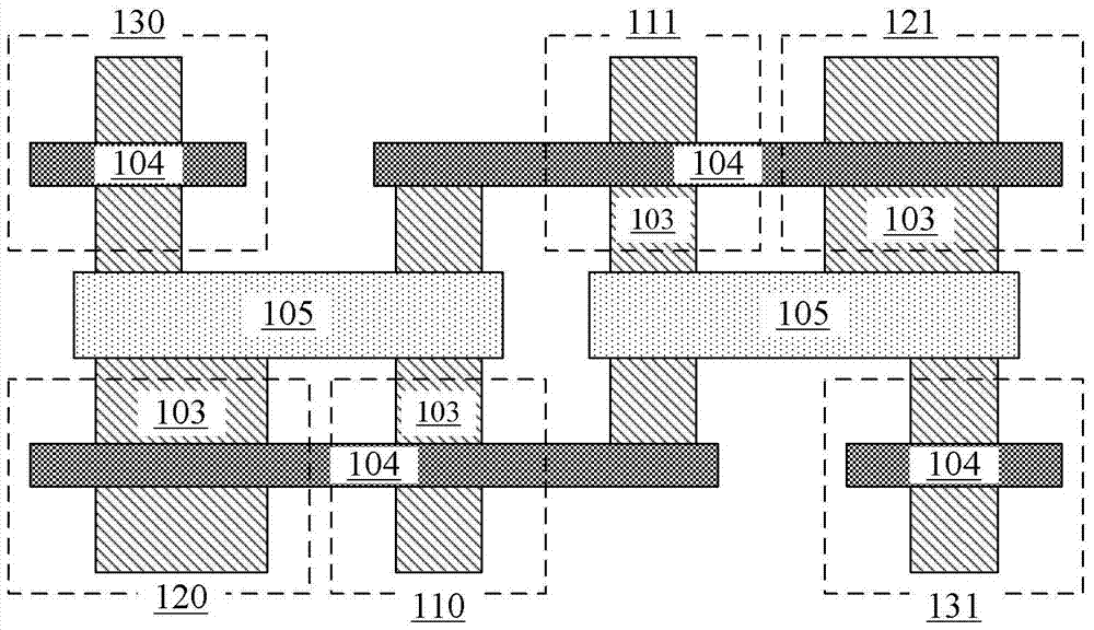
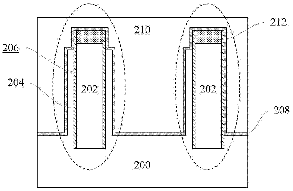
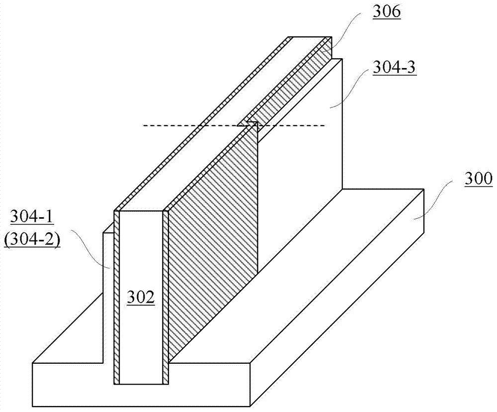
[0018] Hereinafter, embodiments of the present disclosure will be described with reference to the drawings. It should be understood, however, that these descriptions are exemplary only, and are not intended to limit the scope of the present disclosure. Also, in the following description, descriptions of well-known structures and techniques are omitted to avoid unnecessarily obscuring the concept of the present disclosure.

[0019] Various structural schematic diagrams according to embodiments of the present disclosure are shown in the accompanying drawings. The figures are not drawn to scale, with certain details exaggerated and possibly omitted for clarity of presentation. The shapes of the various regions and layers shown in the figure, as well as their relative sizes and positional relationships are only exemplary, and may deviate due to manufacturing tolerances or technical limitations in practice, and those skilled in the art will Regions / layers with different shapes, s...


PUM


Abstract

A semiconductor device and a manufacturing method thereof are disclosed. An example semiconductor device may include: a substrate; first and second back gates formed on the substrate; first fins respectively formed on opposite first and second sides of the first back gate, and A second fin formed on only the first side surface of the second back gate; a first back gate dielectric layer sandwiched between the first back gate and the first fin, and a second fin sandwiched between the second back gate and the second fin the second back gate dielectric layer; and the first gate stack formed on the substrate intersecting the first back gate and the first fin, and the first gate stack formed on the substrate intersecting the second back gate and the second fin There are two gate stacks, and each gate stack is isolated from the corresponding back gate by a dielectric layer.

Description

technical field [0001] The present disclosure relates to the field of semiconductors, and more particularly, to a semiconductor device including fin structures having different driving capabilities and a method of manufacturing the same. Background technique [0002] Compared with conventional transistors, Fin Field Effect Transistors (FinFETs) are increasingly used due to their faster switching speed, higher current density, and better suppression of short-channel effects. In a typical FinFET, the channel is provided in a semiconductor fin (fin). Fins generally comprise single crystal semiconductor material having a substantially rectangular cross-section. The height of the fins is usually greater than the width of the fins to achieve higher conduction current per unit area. [0003] Although FinFETs offer improved performance over conventional metal oxide semiconductor field effect transistors (MOSFETs), they also present some design challenges. Specifically, convention...

Claims


Application Information

Patent Timeline
Patent Type & Authority Patents(China)
IPC IPC(8): H01L29/78H01L21/336H01L29/06
CPCH01L29/7855H01L21/823821H01L27/0924
Inventor 朱慧珑
Owner INST OF MICROELECTRONICS CHINESE ACAD OF SCI
Learn More