Method and system for reducing vacuum consumption in a vehicle

A vehicle and vacuum technology, applied in the direction of vehicle components, transportation and packaging, pump/compressor arrangement, etc., can solve problems such as consumption

Inactive Publication Date: 2015-01-21
FORD GLOBAL TECH LLC
View PDF4 Cites 3 Cited by
  • Summary
  • Abstract
  • Description
  • Claims
  • Application Information

AI Technical Summary

Problems solved by technology

As a result, more vacuum than desired can be consumed when the vehicle is stopped

Method used


Image

  • Method and system for reducing vacuum consumption in a vehicle
  • Method and system for reducing vacuum consumption in a vehicle
  • Method and system for reducing vacuum consumption in a vehicle

Examples


Embodiment Construction

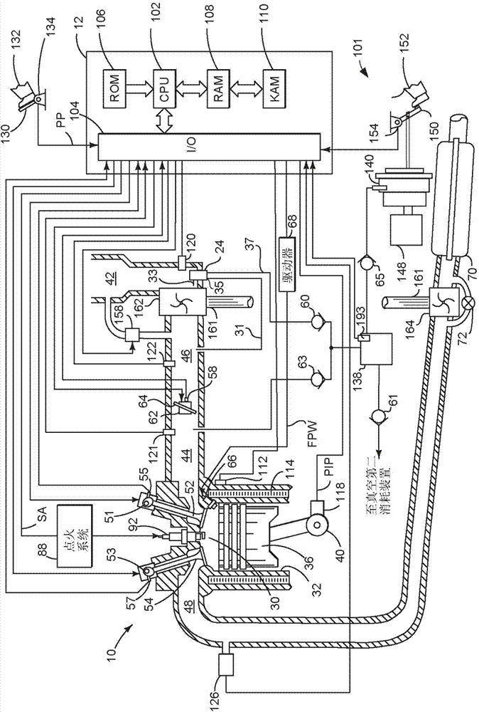
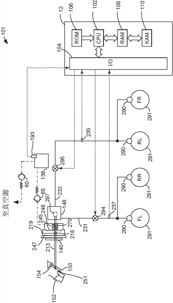
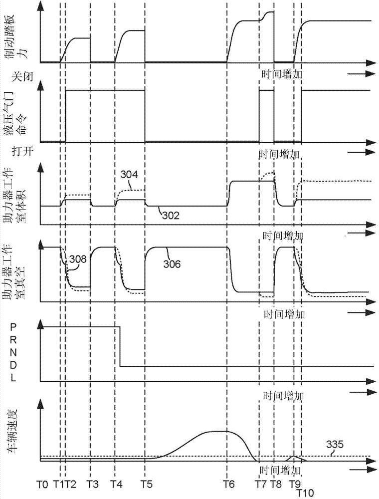
[0014] This description relates to preserving the vacuum of the vehicle. figure 1 and 2 An example system showing vacuum for a vehicle. image 3 An example sequence is shown where vacuum is conserved while operating a vehicle. Figure 4 Shows the method of preserving the vacuum used in the vehicle system.

[0015] refer to figure 1 , an internal combustion engine 10 - comprising a plurality of cylinders, one of which is shown in figure 1 - controlled by the engine electronic controller 12 . Engine 10 includes combustion chamber 30 and cylinder walls 32 with piston 36 positioned therein and connected to crankshaft 40 . Combustion chamber 30 is shown communicating with intake manifold 44 and exhaust manifold 48 via respective intake valve 52 and exhaust valve 54 . Each intake valve and exhaust valve may be operated by an intake cam 51 and an exhaust cam 53 . The position of intake cam 51 may be determined by intake cam sensor 55 . The position of exhaust cam 53 may be de...


PUM


Abstract

A system and method for conserving vacuum within a vehicle is described. In one example, vacuum is conserved via limiting volume expansion of a brake booster working chamber.

Description

technical field [0001] The present application relates to methods and systems for reducing vacuum consumption in vehicles. Background of the invention [0002] Vacuums can be used in vehicles to apply propulsion in vehicle systems. For example, vacuum can be used to apply vehicle brakes, operate turbocharger wastegates and adjust the position of valves in heating and ventilation ducts. However, vacuum in vehicle systems is increasingly a less available resource due to trends in engine downsizing and variable valve timing to improve vehicle fuel economy. [0003] One of the more important consumers of vacuum in a vehicle is the vehicle braking system. The vacuum is used in a brake booster to apply the brakes. Specifically, vacuum is applied to both sides of the brake booster diaphragm when the brakes are not applied. The pressure balance across the diaphragm returns the diaphragm to a position where the piston in the master cylinder does not increase brake line pressure. ...

Claims


Application Information

Patent Timeline
Patent Type & Authority Applications(China)
IPC IPC(8): B60T13/56
CPCB60T8/17B60T13/565B60T13/72B60T8/32B60T13/46B60T17/02B60W10/18
Inventor R·W·坎宁哈姆R·D·普斯夫
Owner FORD GLOBAL TECH LLC
Why Eureka
Try Eureka