Electrical control system of anode assembly casting vehicle and control method of electrical control system

An electrical control system, casting car technology, applied in the directions of transportation and packaging, load hanging components, etc., can solve the problems of step-by-step speed regulation and inaccurate positioning.

Inactive Publication Date: 2015-01-21
LUOYANG XINSILU ELECTRIC
8 Cites 0 Cited by

AI-Extracted Technical Summary

Problems solved by technology

[0005] The main purpose of the present invention is to provide a new electrical control system and control method for the anode assembly casting car by overcoming the problems of the existing control system of the anode assembly casting car, such as stepped spee...

Method used

In one embodiment of the present invention, programmable controller can be the Logix 5000 series programmable controller of AB company, and the programmable controller of this series is integrated with EtherNet/IP communication port, carries out network communication with peripheral equipment , enhance the interlocking function of the system, and improve the stability, flexibility and security of the system.
Meanwhile, programmable controller 11 transmits to dolly frequency converter 122 after switch value signal processing, and dolly motor 42 receives the signal of dolly frequency converter 122, controls the operation of dolly or stops; Simultaneously, programmable controller 11 The analog signal is converted into an accurate 0-10V voltage signal, and then transmitted to the trolley inverter 122. The trolley motor 42 receives the signal from the trolley inverter 122, controls the continuous speed regulation and direction of...

Abstract

The invention discloses an electrical control system of an anode assembly casting vehicle and a control method of the electrical control system. The electrical control system comprises control equipment, operating equipment, position detecting equipment, motors and a direction proportional valve, wherein the control equipment comprises a programmable controller, a frequency converter and a direction valve proportional amplifier; the operating equipment comprises a large vehicle/small vehicle main command controller and a casting main command controller which are respectively provided with a potentiometer and are respectively connected with the programmable controller. The control method comprises the following steps: system starting and continuous speed governing, position detecting, and casting with continuous adjustment on a casting angle and a casting position. The electrical control system is capable of continuously adjusting a speed and accurately positioning the direction and the angle, and is very practical; the casting precision is improved.

Application Domain

Load-engaging elements

Technology Topic

PotentiometerElectrical control +5

Image

  • Electrical control system of anode assembly casting vehicle and control method of electrical control system

Examples

  • Experimental program(1)

Example Embodiment

[0030] In order to further explain the technical means and effects of the present invention to achieve the intended purpose of the invention, the electrical control system and the control method of the anode assembly casting car proposed according to the present invention are specifically implemented below in conjunction with the accompanying drawings and preferred embodiments Ways, methods, steps, features and effects thereof are described in detail below.
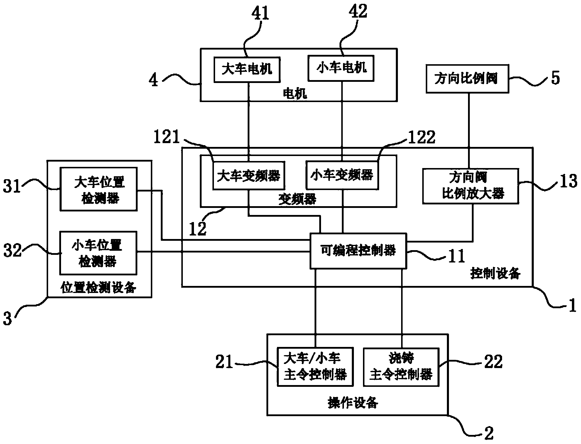
[0031] The core of the present invention is that the owner of the cart/trolley instructs the controller to generate a switch signal and an analog signal, and the programmable controller separately processes the received switch signal and the analog signal and sends them to the The frequency converter is controlled by the programmable controller to drive the operation of the motor, the switch signal controls the start and stop of the motor, and the analog signal controls the continuous speed regulation and direction of the motor , the casting master controller generates a switching signal and an analog signal, the switching signal controls the start and stop of the directional valve proportional amplifier, the analog signal controls the continuous change of the casting angle, and at the same time, the position detection device accurately locates Casting position.
[0032] Specifically, an electrical control system for an anode assembly casting vehicle of the present invention includes a control device 1, an operating device 2, a position detection device 3, a motor 4 and a directional proportional valve 5, the operating device 2, the position detection device 3, The motor 4 and the directional proportional valve 5 are respectively connected with the control device 1 .
[0033] The control device 1 includes a programmable controller 11 , a frequency converter 12 and a directional valve proportional amplifier 13 , mainly to realize functions such as power supply, power drive, control operation, signal collection, processing and transmission. Described frequency converter 12 comprises cart frequency converter 121 and trolley frequency converter 122, and this cart frequency converter 121, this dolly frequency converter 122 and described directional valve proportional amplifier 13 are respectively connected with described programmable controller 11, and described The directional valve proportional amplifier 13 is connected to the directional proportional valve 5, and the directional proportional valve 5 is connected to the casting ladle.
[0034] The operating equipment 2 includes a cart/trolley master controller 21 and a casting master controller 22, and the cart/car master controller 21 and the casting master controller 22 are respectively provided with analog signal generators. The potentiometer, the cart/trolley master controller 21 and the casting master controller 22 are connected to the programmable controller 11 respectively.
[0035] The position detecting device 3 includes a cart position detector 31 and a trolley position detector 32 , and the cart position detector 31 and the trolley position detector 32 are respectively connected to the programmable controller 11 . More specifically, the cart position detector 31 includes three cart position detectors, which are respectively used for deceleration limit, stop limit and limit limit. Described trolley position detector 32 comprises 2 or 3 trolley position detectors, is provided with 2 trolley position detectors, is used for deceleration limit and stop limit respectively, or is provided with 3 trolley position detectors, is respectively used for deceleration Limits, Stop Limits and Limit Limits. In practical applications, setting up two trolley position detectors can meet the needs of general equipment.
[0036]The motor 4 includes a cart motor 41 and a trolley motor 42 , the cart motor 41 is connected to the cart frequency converter 12 , and the trolley motor 42 is connected to the trolley frequency converter 13 . More specifically, there are two cart motors, which can ensure the large-scale operation requirements of the cart, and one trolley motor can meet the small-scale operation requirements of the trolley.
[0037] In the actual control system, the running track of the cart and the trolley can be set as a fixed track. For example, the track of the cart is a longitudinal track to make the cart move forward or backward, and the track of the trolley is a horizontal track to make the trolley move left or right. Right movement, the specific track setting can be flexibly set according to the requirements of the actual control system for casting.
[0038] The control method of the electrical control system of the anode assembly casting car as described above will be described below.
[0039] First, the system is powered on and started, and the cart/trolley owner instructs the controller 21 to output the generated switching signal and analog signal to the programmable controller 11 to control the operation of the cart and the trolley.
[0040] The programmable controller 11 processes the switch signal and transmits it to the cart inverter 121, and the cart motor 41 receives the signal from the cart inverter 121 to control the operation or stop of the cart; at the same time, the programmable controller 11 converts the analog The signal is converted into an accurate 0-10V voltage signal, and then transmitted to the cart inverter 121. The cart motor 41 receives the signal from the cart inverter 121, controls the continuous speed regulation and direction of the cart, and realizes the continuous and accurate movement of the cart .
[0041] When the cart moves to the required station, the cart position detector 31 transmits the position signal of the station to the programmable controller 11, and after the programmable controller 11 processes the received position signal, it sends a control instruction to The cart inverter 121 and the cart motor 41 receive the signal transmitted by the cart inverter 121 to control the cart to stop automatically after deceleration.
[0042] At the same time, the programmable controller 11 processes the switch signal and transmits it to the trolley inverter 122, and the trolley motor 42 receives the signal from the trolley inverter 122 to control the operation or stop of the trolley; at the same time, the programmable controller 11 converts the analog The signal is converted into an accurate 0-10V voltage signal, and then transmitted to the trolley inverter 122. The trolley motor 42 receives the signal from the trolley inverter 122, controls the continuous speed regulation and direction of the trolley, and realizes the continuous and accurate movement of the trolley.
[0043] When the trolley moves to the desired station, the trolley position detector 32 transmits the position signal of the station to the programmable controller 11, and the programmable controller 11 processes the received position signal and sends a control command to the trolley frequency conversion device 122, the dolly motor 42 receives the signal transmitted by the dolly frequency converter 122, and controls the dolly to stop automatically after deceleration;
[0044] Then, casting is carried out, and casting master controller 22 outputs the switching signal and the analog signal output to programmable controller 11; The operation or stop of the directional valve proportional amplifier 13; the programmable controller 11 converts the analog signal into an accurate -10V~10V voltage signal, and then sends a continuous speed regulation command to the directional valve proportional amplifier 13, and the directional proportional valve 5 of the hydraulic station After receiving the signal amplified by the directional valve proportional amplifier 13, the casting angle of the casting ladle is adjusted and controlled quickly and accurately.
[0045] While casting, the cart/trolley owner can command the controller 21 to drive the cart forward or backward, and the trolley to move left or right, so as to run to the required casting position, so as to achieve better casting effect and improve production efficiency.
[0046] In one embodiment of the present invention, the programmable controller can be the Logix 5000 series programmable controller of AB Company, the programmable controller of this series is integrated with EtherNet/IP communication port, carries out network communication with peripheral equipment, enhances the system The interlocking function improves the stability, flexibility and security of the system.
[0047] In a specific embodiment, the frequency converter may be a Siemens MM4 series (such as MM440) frequency converter. MM4 series inverter adopts advanced BICO technology, which not only has reliable operation and convenient maintenance, but also has flexible programming and convenient realization of various functions.
[0048] It should be noted that the programmable controller and frequency converter of the present invention are not limited to the models used in the above embodiments, and any programmable controller and frequency converter that can realize the control function of the present invention can be applied in this system.
[0049] The above description is only a preferred embodiment of the present invention, and does not limit the present invention in any form. Although the present invention has been disclosed as above with preferred embodiments, it is not intended to limit the present invention. Anyone familiar with this field Those skilled in the art, without departing from the scope of the technical solution of the present invention, can use the technical content disclosed above to make some changes or modify them into equivalent embodiments with equivalent changes, but any content that does not depart from the technical solution of the present invention, according to the present invention Any simple modifications, equivalent changes and modifications made to the above embodiments by the technical essence still belong to the scope of the technical solutions of the present invention.

PUM

no PUM

Description & Claims & Application Information

We can also present the details of the Description, Claims and Application information to help users get a comprehensive understanding of the technical details of the patent, such as background art, summary of invention, brief description of drawings, description of embodiments, and other original content. On the other hand, users can also determine the specific scope of protection of the technology through the list of claims; as well as understand the changes in the life cycle of the technology with the presentation of the patent timeline. Login to view more.
Why Eureka
Try Eureka