Screw pin clamping plate joints, independent frame, independent mold frame and construction method of independent mold frame

A technology of screw pin and plywood section, which is applied in the direction of formwork/template/work frame, connection parts of formwork/formwork/work frame, and processing of formwork, which can solve the problems of scattered construction and so on.

Active Publication Date: 2015-01-21
朱宏宇
View PDF8 Cites 8 Cited by
  • Summary
  • Abstract
  • Description
  • Claims
  • Application Information

AI Technical Summary

Problems solved by technology

[0024] The invention provides a screw pin splint joint, an independent frame, an independent formwork and a construction method thereof. It aims to solve the problems of scattered construction, high-altitude operation, turnover of parts, Construction technical problems such as manual handling, to achieve the completion of structural construction with overall equipment and mechanized construction

Method used


Image

  • Screw pin clamping plate joints, independent frame, independent mold frame and construction method of independent mold frame
  • Screw pin clamping plate joints, independent frame, independent mold frame and construction method of independent mold frame
  • Screw pin clamping plate joints, independent frame, independent mold frame and construction method of independent mold frame

Examples


Embodiment 1

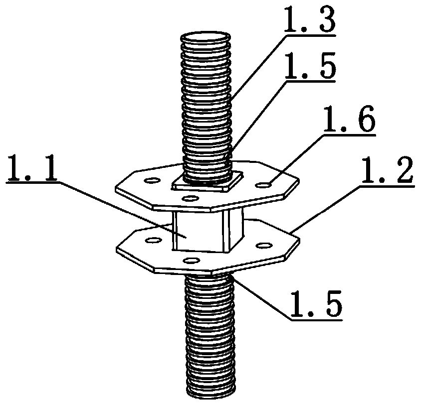
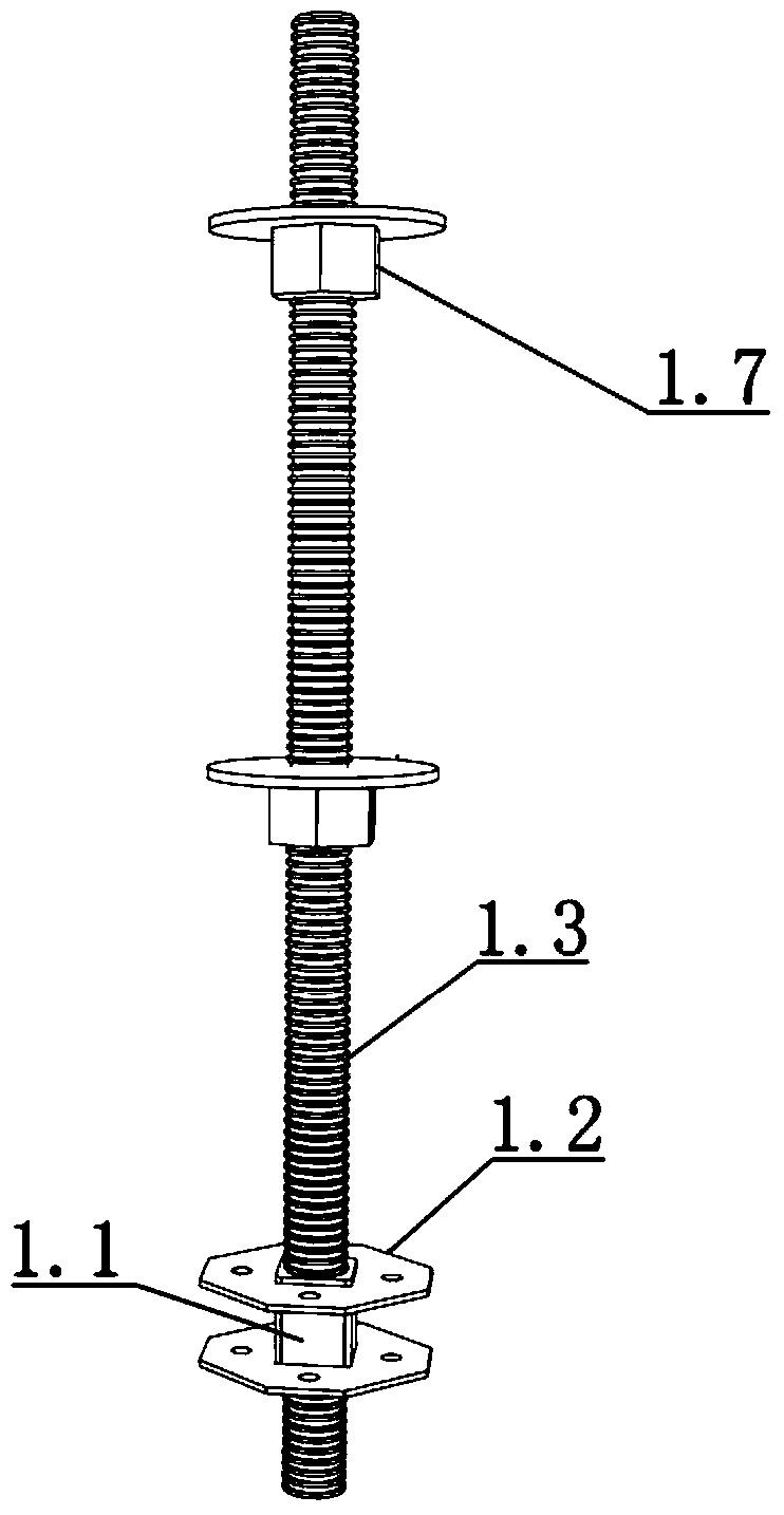
[0209] Example 1 see Figure 1-5 As shown in the screw pin splint section, the screw pin splint section 1 is composed of a joint core 1.1, a splint 1.2 and a screw pin 1.3.

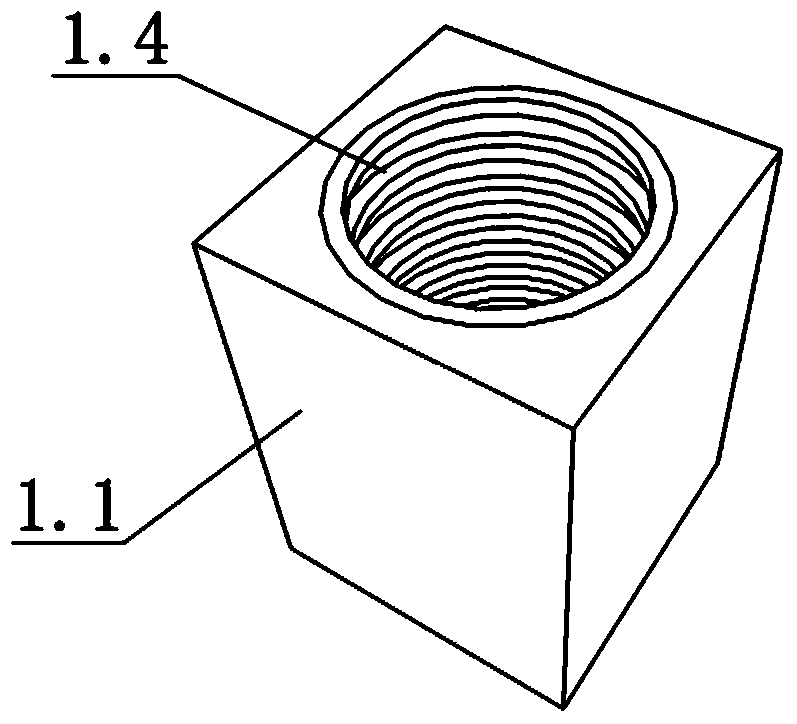
[0210] The joint core 1.1 is a block, a round block or a polygonal block; a screw hole 1.4 is opened on the joint core.

[0211] The screw pin 1.3 is a circular pin, and the screw pin 1.3 is screwed in the screw hole 1.4.

[0212] The upper and lower ends of the screw pin 1.3 protrude from the joint core 1.1 to form a pin joint; the pin joint can be provided with a positioning hole 1.5 or a limited-rotation bayonet.

[0213] The splint 1.2 is composed of two opposite horizontal plates. The horizontal plate protrudes from the side of the joint core 1.1 around the joint core. The horizontal plate includes a square plate, a circular plate or a polygonal plate; The hole sleeve is fixed on the joint core 1.1; the splint 1.2 is provided with connection holes 1.6 corresponding to four directions of the plane, ...

Embodiment 2

[0214] Example 2 see Image 6 , Figure 25-27 As shown, different from Example 1, the joint nucleus 1.1 of Example 2 has a constriction head 1.8 at the upper end, the lower end or the upper and lower ends, and the cross section of the constriction head is quadrilateral or polygonal, with There are external threads; the cross-section of the joint core 1.1 protrudes outward from the cross-section of the shrinking head 1.8, and the protruding part forms a cardan 1.10.

[0215] The splint 1.2 is fixed on the shrinking head 1.8 of the joint core through the core hole, and is fixed by the clamp 1.10.

[0216] On the shrinkage head 1.8, screw the inherent knot nut 1.9.

[0217] The joint core 1.1 and splint 1.2 are connected in series with screw pin 1.3, and fastened with joint core nut 1.9 to form a screw pin splint joint.

[0218] The joint core nut 1.9 is a double-diameter nut, which is screwed on the shrinkage head 1.8 with the large-diameter hole 1.91, and forms a pin hole wi...


PUM


Abstract

The invention provides screw pin clamping plate joints, an independent frame, an independent mold frame and a construction method of the independent mold frame. Each screw pin clamping plate joint is formed by combining a joint core, a clamping plate and a screw pin. The independent frame is a framework unit formed by combining and connecting four vertical rods, eight transverse rods and the four screw pin clamping plate joints or is a splicing framework formed by splicing two or more framework units. The independent mold frame comprises the independent frame, templates and positioning rods. According to the crew pin clamping plate joints, the independent frame, the independent mold frame and the construction method, general accessories are connected to form the plane frame or the stand, the purpose that an integrated mold frame device is formed by combining the frame serving as the mold and the stand serving as the body is achieved, and according to the concrete construction process characteristics, the integrated device is formed through combination and is constructed through big mechanization hoisting. The independent mold frame serves as an auxiliary construction circulation device and is simple, convenient and fast to use, flexible, practical and multiple in purpose and function, the overall process circulation construction of whole preassembling, carrying, hoisting, positioning, sizing, mold assembly, and demolding is finished in a mechanization mode, the carrying frequency is reduced, safe operation is achieved, the loss is avoided, economization and environmental protection are achieved, and precise construction is achieved.

Description

technical field [0001] The invention relates to the technical field of construction equipment for building structures, in particular to construction equipment for cast-in-place reinforced concrete structures and a construction method for the equipment. Background technique [0002] Based on the construction problems of building structures under the current regulations in our country, especially the construction problems of reinforced concrete structures, I have applied for the invention patent Z201310037930. Z201310037858.0 "combined grid scaffolding and its installation and disassembly methods", Z201310037922.5 "plywood joints, structural frames and their installation methods" have made a lot of explanations. [0003] At present, building hoisting machinery and concrete conveying machinery are constantly improving, and the main problems and contradictions in the construction of cast-in-place concrete structures are mostly concentrated in the construction of formwork and sca...

Claims


Application Information

Patent Timeline
Patent Type & Authority Applications(China)
IPC IPC(8): E04G9/00E04G17/00E04G19/00E04G11/40E04G11/48E04G11/08E04G13/02E04G25/04
Inventor 朱宏宇
Owner 朱宏宇
Why Eureka
Try Eureka