Constant temperature control device of combined type fan electronic control system

An electronic control system, constant temperature control technology, applied in the control device, measuring device, coolant flow control and other directions of the cooling device, can solve the problem that the engine cannot effectively solve the problem of low temperature temperature rise and high temperature heat dissipation of the engine, large water and gas temperature deviation, and engine Low thermal efficiency and other problems, to achieve the effect of preventing backflow turbulence, stabilizing the deviation of water and gas temperature, and solving low temperature heating and high temperature heat dissipation

Active Publication Date: 2015-01-21
LONGKOU ZHONGYU THERMAL MANAGEMENT SYST SCIAND TECH
View PDF8 Cites 6 Cited by
  • Summary
  • Abstract
  • Description
  • Claims
  • Application Information

AI Technical Summary

Problems solved by technology

The control strategy of this cooling system cannot distinguish the different working conditions of the engine, and cannot effectively solve the requirements of low temperature heating and high temperature heat dissipation of the engine
This will cause the cooling system to consume large engine power, high fan noise, low thermal efficiency of the engine, large water-air temperature deviation, and low engine life.

Method used


Image

  • Constant temperature control device of combined type fan electronic control system
  • Constant temperature control device of combined type fan electronic control system
  • Constant temperature control device of combined type fan electronic control system

Examples


Embodiment 1

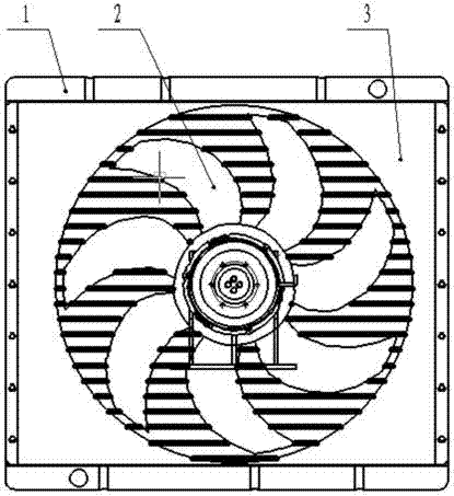
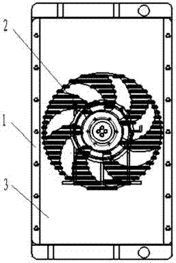
[0064] Example 1, such as Figure 1-3 and 15 as shown:

[0065] The first speed of the two-speed clutch is flexible drive, the clutch output speed is 40%-60% of the input speed, the second speed is rigid drive, the output speed is equal to the input speed. The electronic fan is driven to rotate by the electric energy of the whole vehicle, and at the same time, the number of its work is controlled by the control system.

[0066] The electronic fan and the mechanical fan 2 are respectively arranged before and after the water tank 1, and the mechanical fan 2 is for blowing when the electronic fan is for suction. When the electronic fan is blowing, the mechanical fan 2 is sucking.

[0067] Warming control strategy:

[0068] Assume that the electronic fans 1, 2, 3, and 4 work as ON, and do not work as OFF.

[0069] 1. When the temperature of the engine coolant is very low and does not reach the operating temperature t1 set by the system, the clutch rotates at one speed. Electr...

Embodiment 2

[0075] Example 2, such as Figure 1-3 and 15 as shown:

[0076] Embodiment 2 is improved on the basis of Embodiment 1, and the two-speed clutch is changed to a three-speed clutch.

[0077] Three-speed clutch (the first speed does not transmit working torque, the second speed is flexible drive, the clutch output speed is 40%-60% of the input speed, the third speed is rigid drive, the output speed is equal to the input speed).

[0078] Warming control strategy:

[0079] Assume that the electronic fan is ON when it is working, and OFF when it is not working.

[0080] 1. When the temperature of the engine coolant is very low and does not reach the operating temperature t1 set by the system, the clutch rotates at one speed. Electronic fans are all OFF. At this time, the engine water temperature rises rapidly, and the system basically does not consume engine power.

[0081] 2. When the coolant temperature reaches the working temperature t1 set by the system and does not reach t...

Embodiment 3

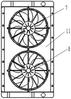
[0091] Example 3, such as Figure 4-6 and 15 as shown:

[0092] The first speed of the two-speed clutch is flexible drive, the clutch output speed is 40%-60% of the input speed, the second speed is rigid drive, the output speed is equal to the input speed.

[0093] The structure of the electronic fan windshield and the mechanical fan windshield is the same as that of Embodiment 1. The sealing method is also the same.

[0094] Warming control strategy:

[0095] Assume that the first and second electronic fans are ON when they are working, and OFF when they are not working.

[0096] 1. When the temperature of the engine coolant is very low and does not reach the operating temperature t1 set by the system, the clutch rotates at one speed. Electronic fans are all OFF. At this time, the engine water temperature rises rapidly, and the system basically does not consume engine power.

[0097] 2. When the coolant temperature reaches the working temperature t1 set by the system an...


PUM


Abstract

A constant temperature control device of a combined type fan electronic control system comprises a water tank and a mechanical fan cowl arranged at the rear end of the water tank, wherein a mechanical fan air inducing ring is arranged on the mechanical fan cowl; a mechanical fan is fixed in the mechanical fan air inducing ring, and electronic fan cowls are arranged at the front end of the water tank; electronic fan air inducing rings are arranged on the electronic fan cowls; electronic fans are fixed to the electronic fan air inducing rings; the mechanical fan is connected with an electronic control clutch, and the electronic control clutch is connected with a belt wheel; the electronic control clutch is fixed to a clutch support. By means of the constant temperature control device of the combined type fan electronic control system, different working conditions of an engine can be distinguished, the requirement for lower temperature rising and high temperature radiating of the engine are effectively met, the engine power consumed by a cooling system is reduced, fan noise is lowered, the heat efficiency of the engine is high, the steam temperature deviation is stable, and the service life of the engine is prolonged.

Description

technical field [0001] The invention relates to an automobile cooling system, in particular to a constant temperature control device for a combined fan electric control system. Background technique [0002] The control strategy of the traditional automobile cooling system is a kind of extensive control strategy, which only aims at keeping the engine from "boiling". The control strategy of this cooling system cannot distinguish different engine working conditions, and cannot effectively solve the requirements of low temperature heating and high temperature heat dissipation of the engine. This will cause the cooling system to consume large engine power, high fan noise, low thermal efficiency of the engine, large water-air temperature deviation, and low engine life. Contents of the invention [0003] Aiming at the deficiencies in the prior art above, the present invention provides a combined fan electric control system constant temperature control device that reduces engine ...

Claims


Application Information

Patent Timeline
Patent Type & Authority Applications(China)
IPC IPC(8): F01P5/02F01P7/12
CPCF01P5/02F01P5/06F01P7/026F01P7/081F01P11/16F01P2005/025F01P2005/046F01P2025/08F01P2037/00F01P2050/22
Inventor 王兆宇邢子义姜文超
Owner LONGKOU ZHONGYU THERMAL MANAGEMENT SYST SCIAND TECH
Why Eureka
Try Eureka