Switching mode power supply input voltage range expansion circuit and design method thereof

An input voltage, switching power supply technology, applied in the protection of under-voltage or no-voltage response, emergency protection circuit device, protection of response to over-voltage, etc. Problems such as narrow protection range and switching power supply limitations

Active Publication Date: 2015-01-21
FENGHUO COMM SCI & TECH CO LTD
View PDF6 Cites 2 Cited by
  • Summary
  • Abstract
  • Description
  • Claims
  • Application Information

AI Technical Summary

Problems solved by technology

In the prior art, the overvoltage and undervoltage protection range of the switching power supply chip in the switching power supply is generally relatively narrow, for example, the common range is about 1V to 4V, and the overvoltage and undervoltage protection range of the switching power supply chip limits the input of the switching power supply. Voltage range, and, in the prior art, a simple resistor series v...

Method used


Image

  • Switching mode power supply input voltage range expansion circuit and design method thereof
  • Switching mode power supply input voltage range expansion circuit and design method thereof
  • Switching mode power supply input voltage range expansion circuit and design method thereof

Examples


Embodiment 1

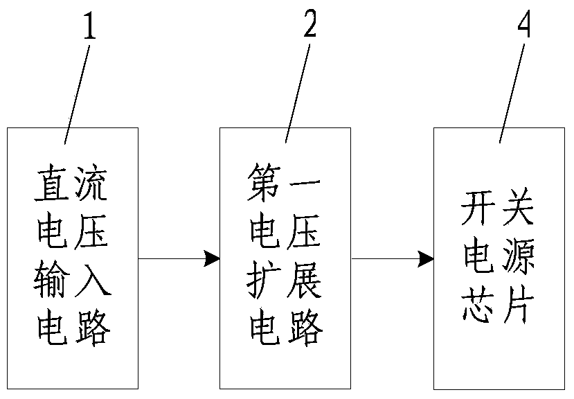
[0047] Such as figure 1 and figure 2 As shown, the switching power supply input voltage range expansion circuit of the present invention includes a first voltage expansion circuit 2 connected between the DC voltage input circuit 1 and the switching power supply chip 4, and the DC voltage input circuit 1 is an AC-DC conversion circuit or DC voltage source, the switching power supply chip 4 has an overvoltage and undervoltage protection terminal, the positive voltage output terminal of the first voltage expansion circuit 2 is connected to the overvoltage and undervoltage protection terminal of the switching power supply chip 4, the first The negative voltage output end of the voltage expansion circuit 2 is connected to the ground end of the switching power supply chip 4 .

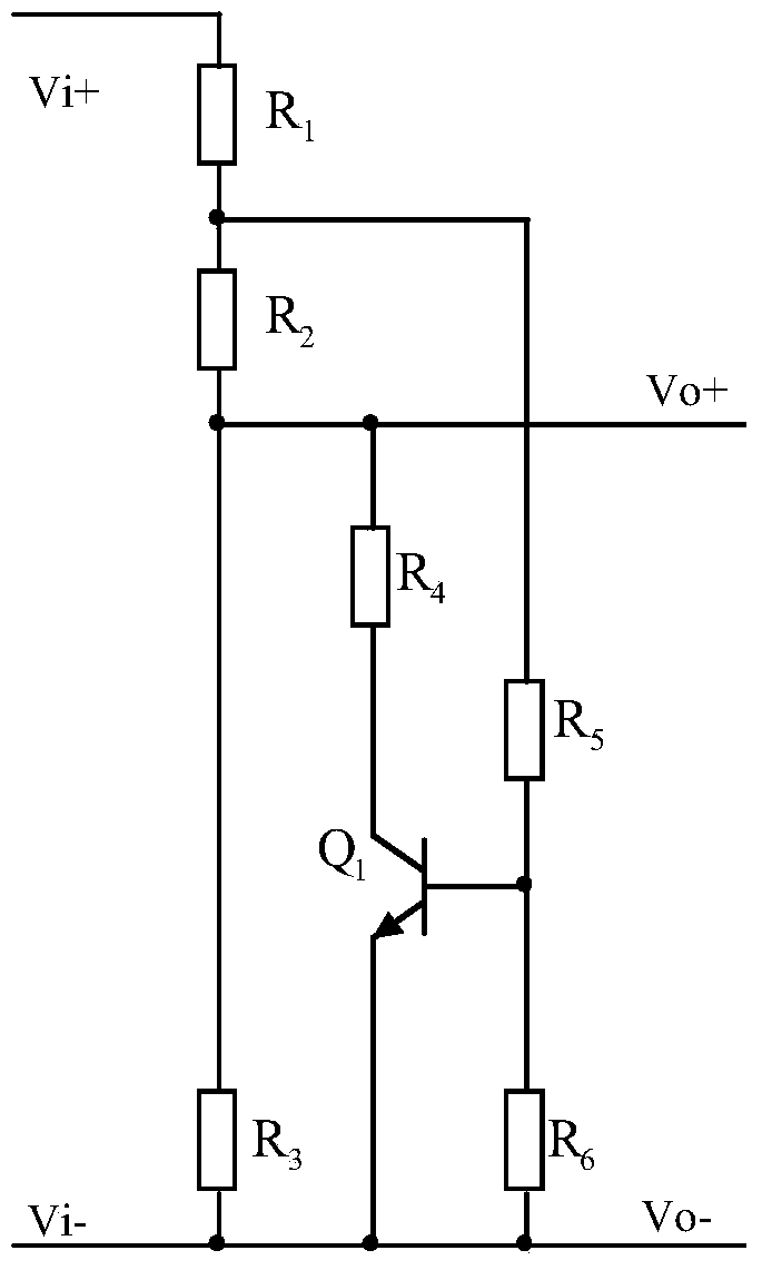
[0048] Such as figure 2 As shown, in this embodiment, the first voltage expansion circuit 2 is composed of a triode Q 1 and the resistor R 1 , R 2 , R 3 , R 4 , R 5 and R 6 composition, the resisto...

Embodiment 2

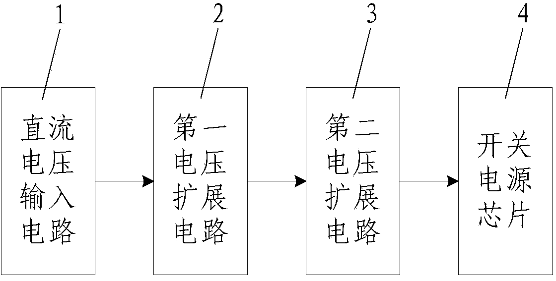
[0074] Such as image 3 and Figure 4 As shown, the difference between the switching power supply input voltage range expansion circuit of this embodiment and embodiment 1 is that the switching power supply input voltage range expansion circuit of the present invention also includes a circuit connected between the first voltage expansion circuit 2 and the switching power supply chip 4 1 second voltage extension circuit 3, the positive voltage input end of the second voltage extension circuit 3 is connected with the positive voltage output end of the first voltage extension circuit 2, the negative voltage input end of the second voltage extension circuit 3 is connected with the first voltage extension circuit The negative voltage output terminals of the voltage expansion circuit 2 are connected, the positive voltage output terminals of the second voltage expansion circuit 3 are connected with the overvoltage and undervoltage protection terminals of the switching power supply ch...

Embodiment 3

[0095] Such as Figure 5 and Figure 6 As shown, the difference between the switching power supply input voltage range expansion circuit of this embodiment and embodiment 2 is that: the number of the second voltage expansion circuit 3 is two, and the positive voltage input terminal of the first second voltage expansion circuit 3 It is connected to the positive voltage output terminal of the first voltage expansion circuit 2, the negative voltage input terminal of the first second voltage expansion circuit 3 is connected to the negative voltage output terminal of the first voltage expansion circuit 2, and the second second voltage The positive voltage input terminal of the expansion circuit 3 is connected to the positive voltage output terminal of the first second voltage expansion circuit 3, and the negative voltage input terminal of the second second voltage expansion circuit 3 is connected to the first second voltage expansion circuit 3 The negative voltage output terminals...


PUM


Abstract

The invention discloses a switching mode power supply input voltage range expansion circuit and a design method of the expansion circuit. The expansion circuit comprises a first voltage expansion circuit connected between a direct current voltage input circuit and a switching mode power supply chip. The direct current voltage input circuit is an alternating current and direct current converting circuit or a direct current voltage source. The switching mode power supply chip is provided with the overvoltage and undervoltage protection end. The positive pole voltage output end of the first voltage expansion circuit is connected with the overvoltage and undervoltage protection end of the switching mode power supply chip. The negative pole voltage output end of the first voltage expansion circuit is connected with the grounded end of the switching mode power supply chip. The invention further discloses the design method of the switching mode power supply input voltage range expansion circuit. According to the expansion circuit and the design method, implementation is convenient, cost is low, the adaptability of a switching mode power supply to a power grid can be improved, the application range of the switching mode power supply is widened, the work reliability of the switching mode power supply can be effectively improved, practicality is high, and application and popularization are convenient.

Description

technical field [0001] The invention belongs to the technical field of switching power supplies, and in particular relates to a switching power supply input voltage range expansion circuit and a design method thereof. Background technique [0002] With the rapid development of science and technology, the relationship between switching power supply and people is getting closer and closer, and it is playing an increasingly important role in people's daily life. In the prior art, the overvoltage and undervoltage protection range of the switching power supply chip in the switching power supply is generally relatively narrow, for example, the common range is about 1V to 4V, and the overvoltage and undervoltage protection range of the switching power supply chip limits the input of the switching power supply. Voltage range, and, in the prior art, a simple resistor series voltage divider circuit is generally connected between the DC voltage input circuit and the switching power sup...

Claims


Application Information

Patent Timeline
IPC IPC(8): H02H7/12H02H3/20H02H3/24
CPCH02H3/20H02H3/24H02H7/1213
Inventor 刘树林付垚张法旺韩跃云刘锦涛张静鹏邓兴旺
Owner FENGHUO COMM SCI & TECH CO LTD
Why Eureka
Try Eureka