Drawing Die Inserting Machine for Motor Stator Core

A technology of motor stator and wire inserting machine, which is applied in the field of drawing die inserting machine, and can solve problems such as complex structure of indexing device, large winding resistance, and unsmooth winding movement

Active Publication Date: 2016-08-10
CHANGZHOU JINKANG PRECISION MECHANISM
View PDF5 Cites 0 Cited by
  • Summary
  • Abstract
  • Description
  • Claims
  • Application Information

AI Technical Summary

Problems solved by technology

However, for large stator cores (with a diameter of more than 500mm), the diameter of the enameled wire in each phase winding is more than 1mm. Therefore, in the wire drawing process, if the winding of each phase is still used as a whole Pulling, not only the resistance of the winding is large, but the movement of the winding in the wire groove is not smooth, resulting in the consequences of pulling the enameled wire in the winding
In addition, because in the process of pulling the wire, when each phase is pulled, the stator core needs to be rotated by an angle through the indexing device to switch to another phase for the wire pulling operation. However, the indexing device of the above-mentioned patent has a complicated structure, and It is controlled by a motor, which increases the difficulty of control

Method used


Image

  • Drawing Die Inserting Machine for Motor Stator Core
  • Drawing Die Inserting Machine for Motor Stator Core
  • Drawing Die Inserting Machine for Motor Stator Core

Examples


Embodiment Construction

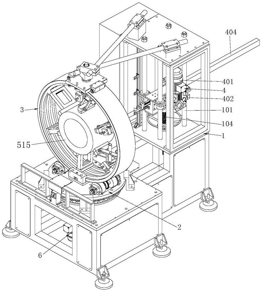
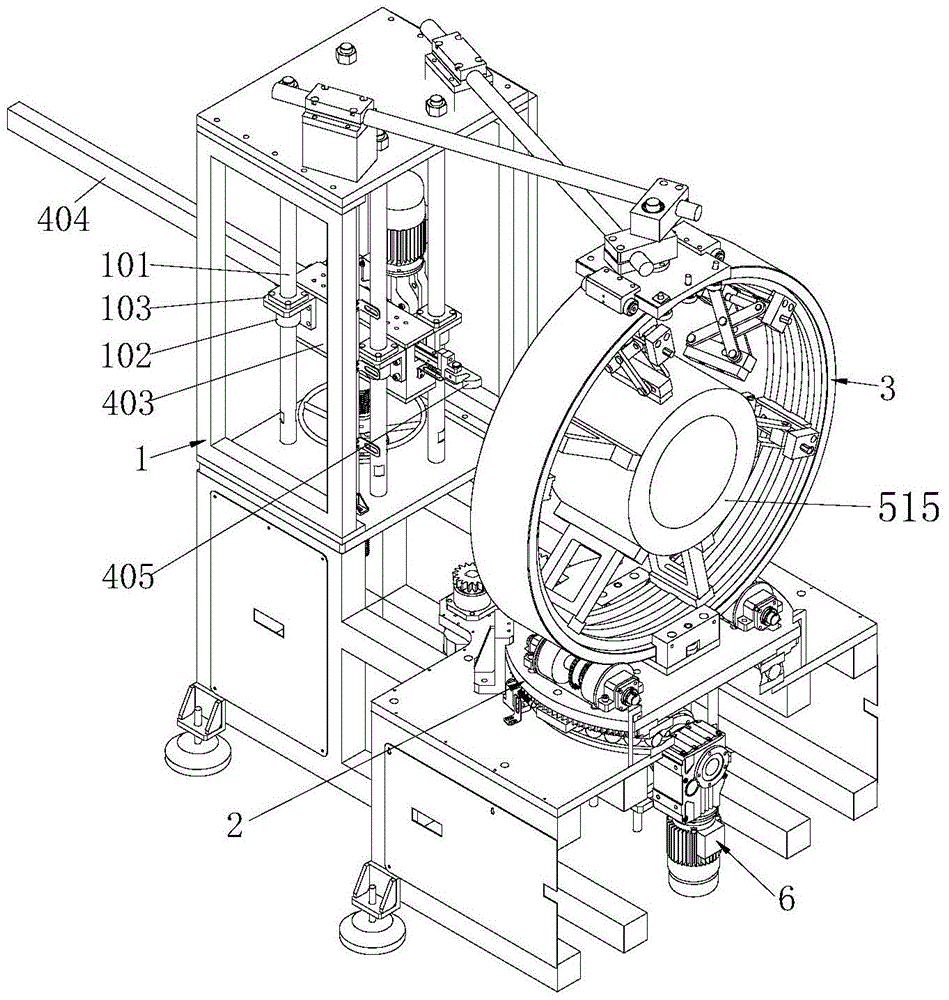
[0038] see figure 1 , a drawing die inserting machine for motor stator core, including a frame 1, a workbench 2 set on the frame, a stator clamping device 3, a wire drawing device 4 that can enter and exit from the stator clamping device, and a wire inserting mold 5 1. The indexing device is composed of 6 parts. The structure of each part will be described in detail below:

[0039] refer to figure 1 , the frame of the present invention is provided with four guide columns 101, a lifting motor (not shown), a first transmission wheel, and a second transmission wheel, each guide column 101 is provided with a linear bearing 102, and a mounting seat 103 It is fixedly connected with each linear bearing 102 . The wire pulling device 4 is fixed on the mounting base 103, and the wire pulling device 4 is threadedly connected with one end of a screw mandrel 104 to form a screw mechanism. Specifically, a nut is installed at the bottom of the casing in the wire pulling device, and the scr...


PUM


Abstract

The invention discloses a drawing die coil inserting apparatus of a motor stator iron core. The drawing die coil inserting apparatus comprises a work bench arranged at a rack, a stator clamping device arranged at a rack and a drawing device can move in and out of the stator clamping device. The stator clamping device is fixed at the work bench. An inserting die includes guide bars, a kidney-shaped pedestal, a kidney-shaped cover plate, a connecting rod, and a locking device; insertion slots are formed in the peripheral surfaces of the pedestal and the cover plate at intervals; and one end of each guide bar is fixed in the insertion slot of the pedestal and the other end of each guide bar is arranged in the insertion slot of the cover plate in a clearance fit mode. A through hole passing through two axial end surfaces of the cover plate is formed in the cover plate. One end of the connecting rod is fixed at the axial end surface, opposite to the cover plate, of the pedestal; and the other end of the connecting rod passes through the through hole of the cover plate and the connecting rod and the cover plate are fastened together by the locking device. Besides, a drag hook seat connecting the drawing device is arranged at the axial end surface, away from the cover plate, of the pedestal. According to the invention, line insertion is carried out on all-phase windings by multiple times, thereby preventing the enameled wires in the windings from being damaged.

Description

technical field [0001] The invention relates to the field of motor stator iron cores, in particular to a drawing die wire inserting machine for motor stator iron cores. Background technique [0002] The winding on the motor stator is the main component of the stator core. The stator winding is connected by the coil group in a certain way to form the stator circuit, and the relative movement with the rotor magnetic flux generates an induced electromotive force to realize the conversion of mechanical energy to electrical energy. According to the shape of coil winding and the way of embedded wiring, it can be divided into two types: centralized and distributed. The winding and embedding of concentrated windings are relatively simple, but the efficiency is low and the operating performance is also poor. Most of the current AC motor stators use distributed windings. According to different models, models and coil embedded winding process conditions, the motors are designed with ...

Claims


Application Information

Patent Timeline
Patent Type & Authority Patents(China)
IPC IPC(8): H02K15/085
Inventor 钟仁康仇永杰
Owner CHANGZHOU JINKANG PRECISION MECHANISM
Why Eureka
Try Eureka