
Method for welding pump and motor for compressor shell

A welding method and compressor pump technology, applied in welding equipment, laser welding equipment, metal processing equipment, etc., can solve the problems of easily damaged compressor casing and motor, restricting production line production efficiency, and prone to danger, so as to avoid Lack of sealing, high strength, and the effect of avoiding damage

Active Publication Date: 2015-01-28
TCL RUIZHI (HUIZHOU) REFRIGERATION EQUIP CO LTD
View PDF7 Cites 3 Cited by
  • Summary
  • Abstract
  • Description
  • Claims
  • Application Information

AI Technical Summary

Problems solved by technology

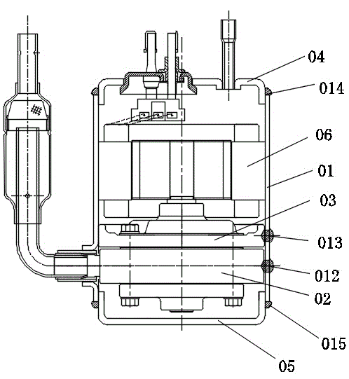
[0005] The compressor casing 01 and the motor 06 are fixed in the form of a thermal sleeve. First, the casing is heated at a high temperature to expand it, and then the motor is placed in the casing. After the casing is cooled, the casing shrinks and the size returns to its original shape; The motor and the compressor shell are interference fit. After the shell is restored to its original shape, the motor is hooped to complete the assembly of the motor; but the heat sleeve is easy to damage the compressor shell and the motor, and the heating process is inevitably accompanied by high current, which is prone to accidents. Dangerous, it takes a long time to cool the shell of the compressor, which seriously restricts the improvement of production line production efficiency

Method used


Image

  • Method for welding pump and motor for compressor shell
  • Method for welding pump and motor for compressor shell

Examples


Embodiment Construction

[0032] In order to facilitate the understanding of those skilled in the art, the present invention will be further described in detail below with reference to the drawings and embodiments.

[0033] Please refer to figure 2 , the embodiment of the present invention includes:

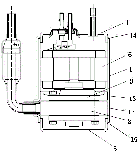
[0034] A welding method for a pump and motor of a compressor shell, using a laser welding device to weld a compressor pump cylinder 2, a pump upper support 3, a top cover 4, a bottom cover 5, and a motor 6 to a compressor shell 1, This laser welding device is the prior art, and is a common laser welding machine circulating on the market. The laser welding device includes a welding head, a gathering lens arranged at the welding head, and the welding method of the compressor shell pump and the motor includes the following steps:

[0035] Step A, laser welding is used to weld the compressor pump cylinder 2 and the pump upper support 3 to the compressor shell 1;

[0036] Step A1, place the compressor pump ...


PUM


Abstract

The invention discloses a method for welding a pump and a motor for a compressor shell. A compressor pump cylinder, a pump upper bracket, a top cover, a bottom cover and the motor are welded on the compressor shell by a laser welding device; the laser welding device comprises a welder and an aggregation lens arranged at the welder. The method for welding the pump and the motor for the compressor shell comprises the following steps: Step A, welding the compressor pump cylinder and the pump upper bracket on the compressor shell by a laser welding technology; Step B, welding the top cover and the bottom cover on the compressor shell by the laser welding technology; Step C, welding the motor on the compressor shell by the laser welding technology. The method for welding the pump and the motor for the compressor shell is novel, high in welding reliability and efficient.

Description

technical field [0001] The invention relates to the field of welding technology, in particular to a welding method for a pump and a motor of a compressor shell. Background technique [0002] With the popularity of electrical equipment such as refrigerators and air conditioners, the demand for compressors has also surged, and at the same time, it is accompanied by higher quality requirements for compressors. [0003] refer to figure 1 , in the traditional compressor manufacturing, the welding between the compressor casing 01 and the compressor pump cylinder 02 and the pump upper support 03 is welded by welding rod spot welding; because the welding method of welding rod spot welding requires The welding work can only be completed by putting the electrode deep into the welding spot area, so it is necessary to drill multiple welding holes in the shell, such as figure 1 The welding hole 012 and the welding hole 013 in the welding hole, the welding rod is spot-welded at the weld...

Claims


Application Information

Patent Timeline
Patent Type & Authority Applications(China)
IPC IPC(8): B23K26/21B23K26/14
CPCB23K26/14B23K26/20
Inventor 邱忠本高祥洪稚鹏
Owner TCL RUIZHI (HUIZHOU) REFRIGERATION EQUIP CO LTD
Learn More