Miniature multifunctional combined machining center

A compound machining center and multi-functional technology, applied in the field of CNC machine tools, can solve the problems of inability to provide space and foundation requirements for industrial machining centers, monotonous functions of industrial machining centers, poor efficiency and stability, etc., to achieve rich functions, flexible and controllable structure , The effect of improving the utilization rate

Inactive Publication Date: 2015-01-28
续宗耀
View PDF8 Cites 7 Cited by
  • Summary
  • Abstract
  • Description
  • Claims
  • Application Information

AI Technical Summary

Problems solved by technology

[0003] Most of the processing center equipment in the prior art is designed for industrial production and processing. It is bulky and weighs several tons. Ordinary home manufacturing enthusiasts or school laboratories generally cannot provide the space and foundation required by industrial processing centers. Requirements: Three-phase power supply must be used for power supply. Even if phase-changing equipment is installed, the power of the industrial processing center cannot be borne by the lighting power supply; the design purpose of the industrial processing center is for production use, and its structural features are high efficiency and high stability. , the more functions of the machine tool, the worse its efficiency and stability, so the functions of industrial machining centers are often more monotonous

Method used


Image

  • Miniature multifunctional combined machining center
  • Miniature multifunctional combined machining center
  • Miniature multifunctional combined machining center

Examples


Embodiment Construction

[0035] The present invention will be described in detail below in conjunction with the accompanying drawings.

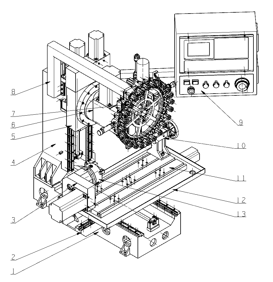
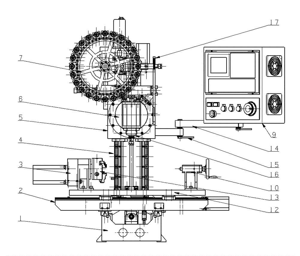
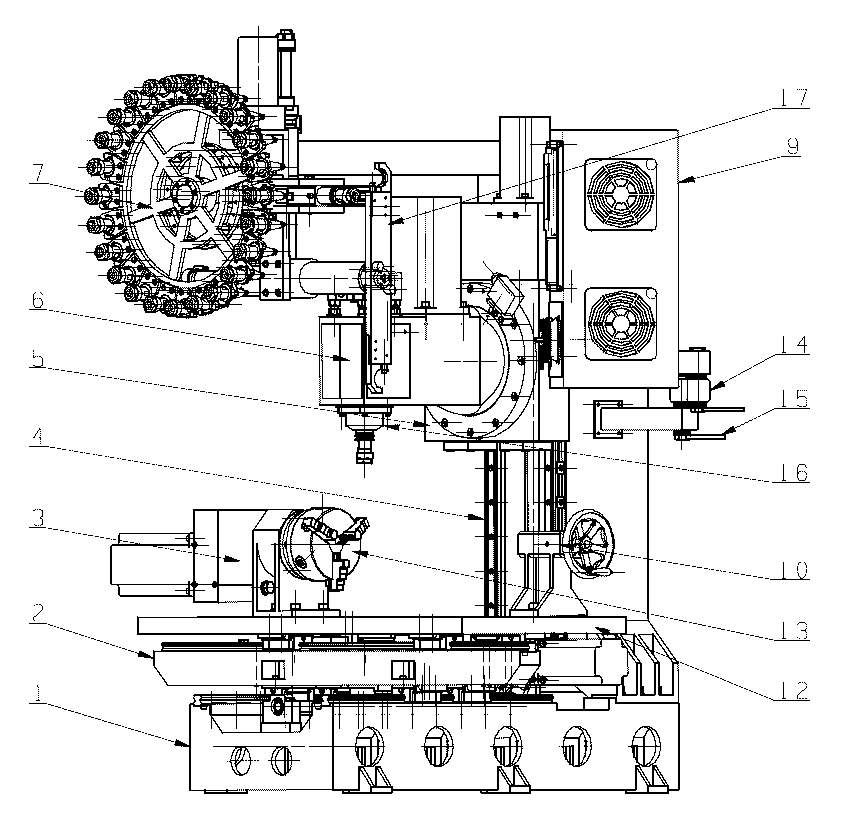
[0036] Such as figure 1 As shown, the present invention includes a machine tool base 1, an X-axis ram 2, a turning spindle (A-axis assembly) 3, a machine column 4, a B-axis worm gear box assembly 5, a headstock assembly 6, a tool magazine 7, a tool magazine bracket 8, CNC system 9, tail seat 10, worktable 11, oil pan 12, chuck 13, CNC system support 14, CNC system support locking mechanism 15, tool spindle 16, automatic tool exchange device mechanical arm 17, of which: workbench 11 X-axis moving part of the machine tool, X-axis ram 2 is the Y-axis moving part of the machine tool, B-axis worm gear box assembly 5 is the Z-axis moving part, chuck 13 is the A-axis moving part of the machine tool, and headstock assembly 6 is the B-axis movement part.

[0037] The tool magazine 7 is installed on the front of the machine tool, the headstock assembly 6 is at the highest po...


PUM


Abstract

The invention discloses a miniature multifunctional combined machining center. The miniature multifunctional combined machining center comprises a tool magazine, a numerical control system, two spindles, three degree-of-freedom feed shafts and two degree-of-freedom rotating shafts, wherein the tool magazine is arranged on the front of a machine tool and at the highest point in right front of a spindle box, and an automatic tool exchange device mechanical arm of the tool magazine is longitudinally arranged on the right side of the machine tool; the numerical control system is arranged on the right side of the machine tool, is connected to the machine tool through a two-section connecting rod mechanism and can freely move in the movement range of the connecting rod mechanism; the connecting rod mechanism can be locked by a locking handle to fix the position of the numerical control system; the three degree-of-freedom feed shafts are respectively a shaft X, a shaft Y and a shaft Z; the two degree-of-freedom rotating shafts are respectively a shaft A and a shaft B; the shaft A also serves as a turning spindle and can be detached to increase the effective travel of a workbench and the shaft X of the machine tool. The miniature multifunctional combined machining center has the characteristics that the miniature multifunctional combined machining center is small in size and light in weight, can be placed at any place and can be used in a storied house; the miniature multifunctional combined machining center is low in power consumption and can be directly powered by a lighting source; the miniature multifunctional combined machining center is rich in functions and flexible and controllable in structure, comprises the tool magazine, can automatically exchange tools, can realize five-shaft linkage, and can complete turning, milling, boring, planing, grinding, slotting, drilling, tapping, hobbing and other machining processes.

Description

technical field [0001] The invention belongs to the field of numerical control machine tools, and in particular relates to a miniature multifunctional composite machining center. Background technique [0002] The machining center is a highly automated mechanical processing equipment. Its characteristics are: it has a tool magazine, which can complete the automatic tool change work. After the workpiece is clamped once, according to the pre-programmed NC machining program, the machine tool can automatically select the processing method, change the tool, Automatic tool setting, automatic change of spindle speed, feed rate, etc., can continuously complete a variety of processes, reducing the time for auxiliary processes such as workpiece clamping, measurement and machine tool adjustment. [0003] Most of the processing center equipment in the prior art is designed for industrial production and processing. It is bulky and weighs several tons. Ordinary home manufacturing enthusias...

Claims


Application Information

Patent Timeline
Patent Type & Authority Applications(China)
IPC IPC(8): B23Q37/00
CPCB23Q37/00
Inventor 续宗耀
Owner 续宗耀
Why Eureka
Try Eureka