Co-location device for automatically butting and assembling large-sized thin-wall barrel-shaped members

A technology of co-location and automatic docking, applied in the field of devices in the field of assembly and docking technology, can solve the problems of not meeting the requirements of modern production, high initial positioning requirements of parts to be assembled, distortion and deformation of thin-walled parts, etc., so as to improve docking efficiency and docking. Accuracy, solving the effect of uneven quality of components and small flexible deformation

Inactive Publication Date: 2015-01-28
SHANGHAI JIAO TONG UNIV
View PDF6 Cites 30 Cited by
  • Summary
  • Abstract
  • Description
  • Claims
  • Application Information

AI Technical Summary

Problems solved by technology

However, this technology lacks rotating joints, and the deviation of the attitude adjustment of the front and rear brackets may cause distortion and deformation of thin-walled parts; the attitude adjustment has too high requirements for the initial positioning of the parts to be assembled; the visual and manual attitude adjustment accuracy is poor and the efficiency is low, which cannot meet the requirements of modern production

Method used


Image

  • Co-location device for automatically butting and assembling large-sized thin-wall barrel-shaped members
  • Co-location device for automatically butting and assembling large-sized thin-wall barrel-shaped members
  • Co-location device for automatically butting and assembling large-sized thin-wall barrel-shaped members

Examples


Embodiment 1

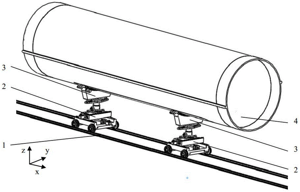
[0036] Such as figure 1 As shown, in this embodiment, two sets of positioning mechanisms 2 that are movable on the track 1 and have a C-shaped bracket 3 are fixedly connected with the component 4 to be adjusted.

[0037] Such as Figure 4 As shown in -6, the positioning mechanism 2 includes: a sliding chassis 5, a lateral attitude adjustment platform 6, a vertical attitude adjustment platform 7 and a rotating attitude adjustment platform 8, wherein: the sliding chassis 10 with a screw mechanism 12 has x In the attitude adjustment function, the lower part of the horizontal attitude adjustment platform 6 is connected to the x-direction moving pair through the guide rail slider 11 and the sliding chassis guide rail 18, which is driven by the screw mechanism 12; The platform 6 rails are connected to form a y-movable pair, which is driven by a screw mechanism 12;

[0038] A sliding wheel set 9 is provided below the sliding chassis 5, and the sliding wheel set 9 is in rolling cont...

Embodiment 2

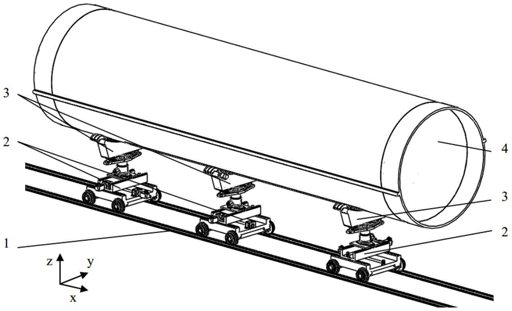
[0050] Such as figure 2 As shown, this embodiment is realized by three sets of positioning mechanisms 2. The coordinated positioning device composed of the three sets of positioning mechanisms has at least six active driving combinations, and the driving form is 2‐2‐2 arrangement (the first positioning mechanism yz active drive, the second positioning mechanism xz is actively driven, and the third positioning mechanism yz is actively driven); in addition, one of the three C-shaped brackets 3 needs to have an active drive.

[0051] In this embodiment, the overall layout of the tooling is as follows figure 2 As shown, the positioning mechanism such as Figure 4 As shown in -6, the screw mechanism driven by the motor has the function of adjusting the attitude in this direction. The positioning mechanisms along the x-axis direction are the first positioning mechanism, the second positioning mechanism, and the third positioning mechanism. The structure diagram of the C-shaped br...

Embodiment 3

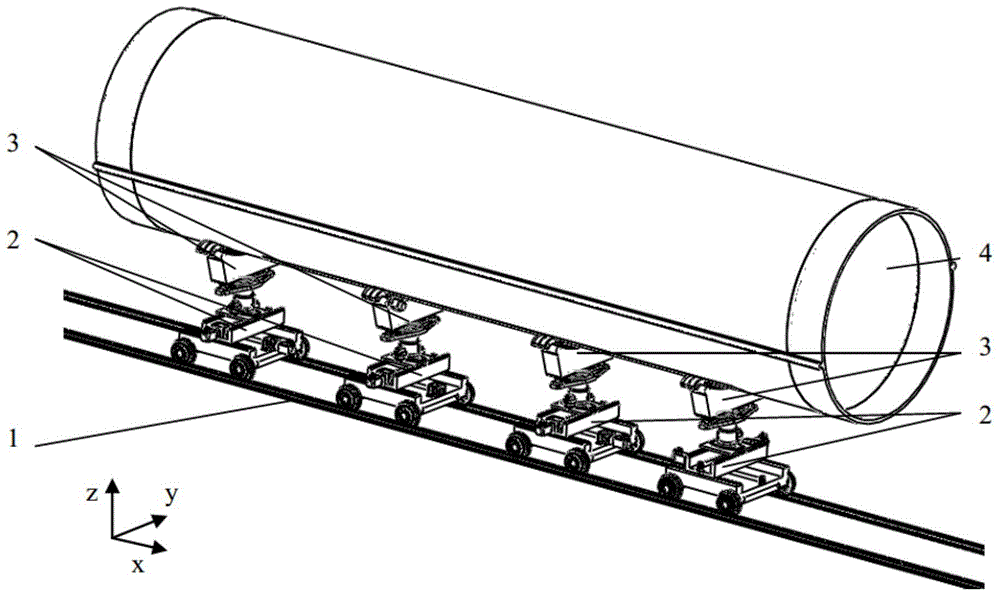
[0059] Such as image 3 As shown, the present embodiment adopts four sets of positioning mechanisms 2 to realize. The cooperative positioning device composed of the four sets of positioning mechanisms has at least seven active driving combinations, and the driving form is 2-2-1-2 arrangement (the first positioning mechanism yz is actively driven, the second positioning mechanism xz is actively driven, the third positioning mechanism z is actively driven, and the fourth positioning mechanism yz is actively driven); in addition, one of the four C-shaped brackets 3 needs to have an active drive.

[0060] In this embodiment, the overall layout of the tooling is as follows image 3 As shown, the positioning mechanism such as Figure 4 As shown in -6, the screw mechanism driven by the motor has the function of adjusting the attitude in this direction. The positioning mechanisms along the x-axis direction are the first positioning mechanism, the second positioning mechanism, the thi...


PUM


Abstract

The invention discloses a co-location device for automatically butting and assembling large-sized thin-wall barrel-shaped members and belongs to the field of assembling butting technologies. The co-location device comprises at least two sets of location mechanisms fixedly connected with the large-sized thin-wall barrel-shaped members to be assembled respectively, wherein each location mechanism comprises a slide chassis, a transverse posture adjustment platform, a vertical posture adjustment platform and a rotary posture adjustment platform. The device has the advantages of high operation precision, high automation level, large bearing capacity, high response speed and wide motion range, and can be used for accurately butting and assembling the large-sized thin-wall barrel-shaped members.

Description

technical field [0001] The invention relates to a device in the technical field of assembly and docking, in particular to a six-degree-of-freedom cooperative positioning device for automatic docking and assembly of large thin-walled cylindrical components. Background technique [0002] At present, the assembly and docking of large thin-walled parts in China mainly relies on visual inspection and hand cranking to ensure the adjustment and coordination of parts. Usually, the two components are respectively placed on the bracket or the trailer platform, and there is a circle of corresponding hole pin matching structures on the butt ring surface of the two components. Push one part slowly close to the other part, observe and manually adjust the posture of the corresponding hole pin, and insert it after alignment. This method leads to low matching accuracy of the butt face pins, large assembly stress, affects fatigue strength, and low efficiency. Aiming at this problem, a six-d...

Claims


Application Information

Patent Timeline
Patent Type & Authority Applications(China)
IPC IPC(8): B25B11/00B23P19/00
CPCB23P19/10B25B11/00
Inventor 王皓来新民赵勇孔令雨陈根良王卓识
Owner SHANGHAI JIAO TONG UNIV
Why Eureka
Try Eureka