Safety valve liquid return system and integrated safety valve liquid return valve block

A safety valve and liquid return valve technology, which is applied to the safety of fluid pressure actuation systems, fluid pressure actuation devices, mining equipment, etc. The effect of convenient maintenance, realization of system liquid return circulation, and high degree of design integration

Active Publication Date: 2015-01-28
BEIJING TIANMA INTELLIGENT CONTROL TECH CO LTD
View PDF6 Cites 2 Cited by
  • Summary
  • Abstract
  • Description
  • Claims
  • Application Information

AI Technical Summary

Problems solved by technology

In this way, during the opening process of the safety valve, the discharged liquid will not only affect the sealing and normal operation of electrical products, but also cause pollution to the surface water environment; at the same time, the traditional safety valve liquid return system mainly uses pipelines to connect the main valve liquid return port Connected to the tail end of the safety valve, not only the pipeline layout is complicated, but also the structure is unstable, maintenance is inconvenient, the flow resistance is too large, and the cost is high

Method used


Image

  • Safety valve liquid return system and integrated safety valve liquid return valve block
  • Safety valve liquid return system and integrated safety valve liquid return valve block
  • Safety valve liquid return system and integrated safety valve liquid return valve block

Examples


Embodiment Construction

[0026] The present invention will be further described in detail below in terms of specific embodiments in conjunction with the accompanying drawings.

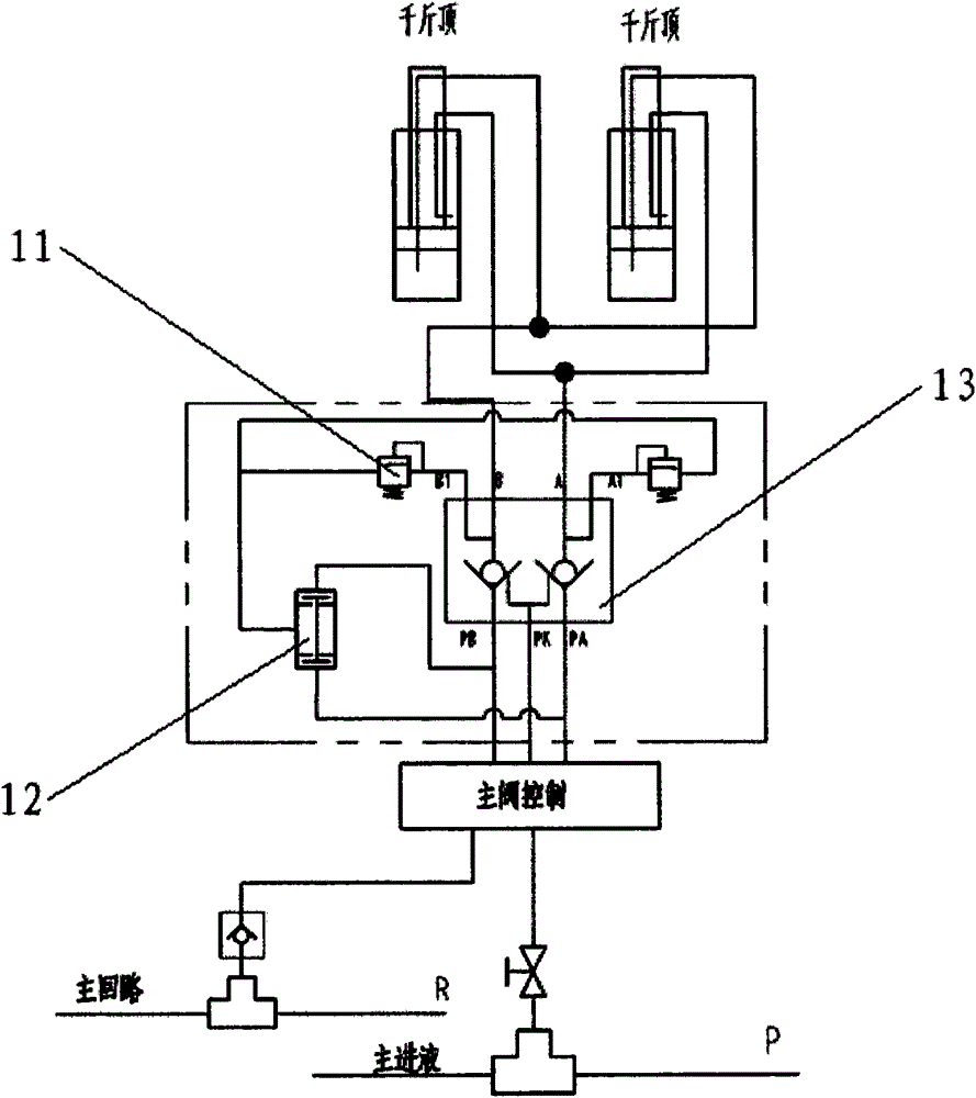
[0027] See attached figure 1 , which describes the system principle of the safety valve liquid return system according to the present invention. The safety valve liquid return system is used for the safety valve liquid return control of the coal mine underground hydraulic system, as attached figure 1 As shown in the part in the dotted line box, it includes two safety valves, two-way hydraulic control two-way lock and three-way logic valve. The liquid outlets of the two safety valves are respectively in fluid communication with the liquid passage chamber of the three-way logic valve; the three-way logic valve includes A chamber and B chamber, and the A chamber is in fluid communication with or fluidly blocked from the liquid passage chamber through the movable plug component A , chamber B is in fluid communication or fluid is...


PUM


Abstract

The invention discloses an integrated safety valve liquid return valve block which comprises a valve body, two paths of hydraulic control two-way lock valve elements and two cartridge safety valves, wherein liquid inlets P of the two cartridge safety valves are communicated with a liquid outlet A of the path A and a liquid outlet B of the path B through a passage formed in the valve body respectively, and liquid outlets T of the two cartridge safety valves are in fluid communication with a liquid passing cavity Q of a cartridge alternate valve through the passage formed in the valve body; the cartridge alternate valve is matched with the valve body to form cavities A and B; a liquid return opening A is formed in a valve wall between the cavity A and the liquid passing cavity Q, and a liquid return opening B is formed in the valve wall between the cavity B and the liquid passing cavity Q; the cavity A is in fluid communication with the liquid inlet A of the path A, and the cavity B is in fluid communication with the liquid inlet B of the path B. According to the integrated safety valve liquid return valve block, the cartridge safety valve and the cartridge alternate valve are integrated on the basis of the conventional double-hydraulic control or single-hydraulic control two-way lock, the system structure is basically designed and laid out on the premise of recovering return liquid of the safety valves, the arrangement of a pipeline is avoided, system return liquid is recycled, and the integrated safety valve liquid return valve block is easy to mount, high in design integration degree, convenient to troubleshoot and overhaul and reasonable in layout.

Description

technical field [0001] The invention relates to a liquid return system for a safety valve, in particular to a liquid return system for a safety valve used in fully mechanized mining face equipment such as a support jack, and an integral liquid return valve block for the safety valve formed by an integrated design. Background technique [0002] The safety valve is an automatic pressure relief device driven by medium pressure. As a protective component of the hydraulic support, it has the characteristics of high safety margin, fast response, reliable sealing form, and strong anti-pollution ability. It is mostly used in the lower cavity of the column, balance The upper and lower chambers of the jack, the piston chamber or piston rod chamber of the push jack, etc. The performance of the safety valve directly affects the normal operation of the hydraulic support and the safety of personnel. With the application of the large mining height and caving support, the working resistance...

Claims


Application Information

Patent Timeline
Patent Type & Authority Applications(China)
IPC IPC(8): F15B20/00F15B13/02
CPCE21D23/16F15B13/02F15B20/005F15B2013/002
Inventor 周如林刘晓萌王伟徐鹏吴会刚王巍
Owner BEIJING TIANMA INTELLIGENT CONTROL TECH CO LTD
Why Eureka
Try Eureka