
Waste heat heating system of cremation machine

A technology for a heating system and a cremator is applied in the field of the waste heat heating system of the cremator, which can solve problems such as energy waste, and achieve the effects of high utilization rate of waste heat and novel structure.

Inactive Publication Date: 2015-01-28
WEIHAI LUYUAN ENVIRONMENTAL PROTECTION EQUIP SCI & TECH
View PDF0 Cites 1 Cited by
  • Summary
  • Abstract
  • Description
  • Claims
  • Application Information

AI Technical Summary

Problems solved by technology

[0002] We know that the temperature of the cremation flue gas can reach 400-600°C, and the flue gas is directly cooled by the flue gas cooling method, resulting in a serious waste of energy

Method used


Image

  • Waste heat heating system of cremation machine
  • Waste heat heating system of cremation machine

Examples


Embodiment Construction

[0012] The present invention will be further described below in conjunction with accompanying drawing:

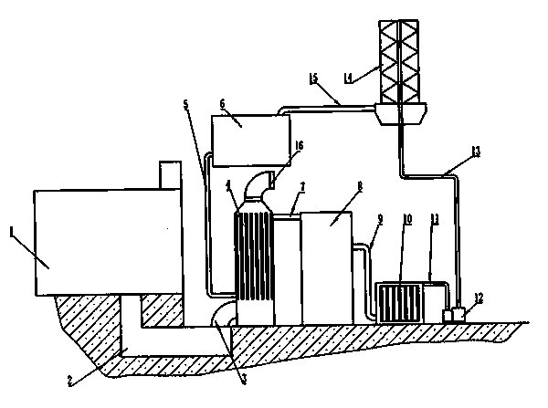
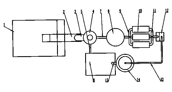
[0013] Such as figure 1 , figure 2 As shown, the present invention relates to a cremation machine waste heat heating system, which is composed of a cremation machine 1, an underground flue 2, a heat exchange system, a heating system, and a cooling system. The heat exchange system is composed of a smoke inlet pipe 3 and a smoke outlet pipe. 16. Composed of heat exchanger 4, heat exchanger inlet pipe 5, heat exchanger outlet pipe 7, and energy storage tank 8, which is characterized in that the high-temperature flue gas of the cremation machine passes through the underground flue 2, the smoke inlet pipe 3 and the heat exchanger 4 The bottom is connected, and the smoke outlet pipe 16 is connected with the exhaust gas purification treatment system; the heat exchanger inlet pipe 4 is connected with the lower left part of the heat exchanger 4, and the normal temperature water en...


PUM


Abstract

The invention relates to a waste heat heating system of a cremation machine. The system consists of the cremation machine, an underground flue, a heat exchange system, a heating system and a cooling system, and is characterized in that high-temperature flue gas of the cremation machine is connected with the bottom of a heat exchanger through the underground flue and a flue gas inlet pipe, and a flue gas outlet pipe is connected with a tail gas purification treatment system; a heat exchanger water inlet pipe is connected with the left lower part of the heat exchanger; normal temperature water enters a longitudinal tube in the heat exchanger through the heat exchanger water inlet pipe to perform heat exchange with the high-temperature flue gas in the heat exchanger to preheat the normal temperature water to 100 DEG C; high-temperature water enters an energy storage tank for providing heat energy for the heating system through a heat exchanger water outlet pipe; the high-temperature water in the energy storage tank enters a radiator under the action of a circulating pump through a hot water pipe to perform heat exchange with air so as to achieve the purpose of waste heat heating; the water after heat exchange of the radiator and the air enters a condensing tower through a condensing tower water inlet pipe under the action of the circulating pump, is cooled in the condensing tower, then enters a water tank through a condensing tower water outlet pipe and finally enters the heat exchanger through the heat exchanger water inlet pipe to perform heat exchange.

Description

technical field [0001] The invention relates to the field of heating, in particular to a cremation machine residual heat heating system. Background technique [0002] We know that the temperature of the cremation flue gas can reach 400-600°C, and the flue gas is directly cooled by the flue gas cooling method, resulting in a serious waste of energy. Contents of the invention [0003] The technical problem to be solved by the present invention is to overcome the deficiencies of the above-mentioned prior art and provide a cremation machine waste heat heating system to provide heating facilities for offices and improve the utilization rate of cremation waste heat. [0004] The technical solution adopted by the present invention to solve the above technical problems is: a cremation machine residual heat heating system, which is composed of a cremation machine, an underground flue, a heat exchange system, a heating system, and a cooling system, and is characterized in that: the ...

Claims


Application Information

Patent Timeline
Patent Type & Authority Applications(China)
IPC IPC(8): F24D11/00
Inventor 丁冲刘启宏于勇
Owner WEIHAI LUYUAN ENVIRONMENTAL PROTECTION EQUIP SCI & TECH
Learn More