
Direct current superposition method measurement circuit

A technology of DC superposition method and measurement circuit, which is applied in the direction of measuring electricity, measuring devices, and measuring electrical variables, etc., can solve the problems of substation relay misoperation, weak current, instability, etc., to avoid vicious grounding and short-circuit faults, The effect of high accuracy and simple wiring

Inactive Publication Date: 2015-01-28
SHANGHAI MUNICIPAL ELECTRIC POWER CO
View PDF5 Cites 4 Cited by
  • Summary
  • Abstract
  • Description
  • Claims
  • Application Information

AI Technical Summary

Problems solved by technology

However, the current measured by the DC component method is extremely weak and unstable, and a small disturbance will cause a large error. The on-line monitoring of cables will be interfered by contact potential, leakage current and noise, which will easily cause large errors, and when the DC current passes through the substation grounding transformer (GPT) for a long time, the magnetic circuit of the substation grounding transformer will be saturated The zero-sequence voltage is generated and damaged, which in turn causes the substation relay to malfunction

Method used


Image

  • Direct current superposition method measurement circuit
  • Direct current superposition method measurement circuit

Examples


Embodiment Construction

[0017] In order to better understand the technical solution of the present invention, the inventor of the present invention will describe in detail below in conjunction with the accompanying drawings through specific embodiments:

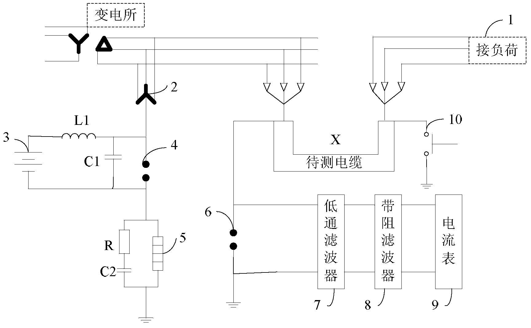
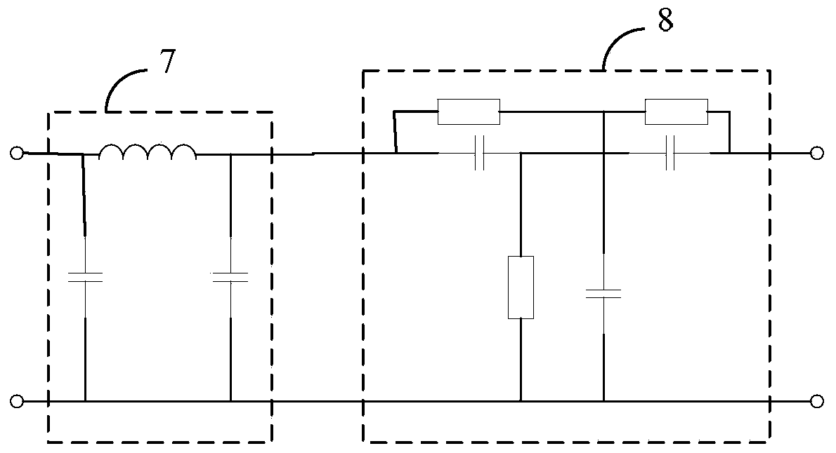
[0018] see figure 1 , an embodiment of the present invention, a DC superposition method measurement circuit, including the cable X to be tested connected between the load 1 and the busbar of the substation grounding transformer 2, and also includes a DC power supply 3, a first inductance L1, a first Capacitor C1 , first surge protector 4 , transformer grounding protection circuit, second surge protector 6 , low pass filter 7 , band stop filter 8 , ammeter 9 and relay 10 .

[0019] One end of the DC power supply 3, the first inductance L1, the first capacitor C1 and the other end of the DC power supply 3 are sequentially connected; after one end of the first surge protector 4 is connected to the connecting end of the first inductance L1 and the first...


PUM


Abstract

The invention discloses a direct current superposition method measurement circuit. The direct current superposition method measurement circuit comprises a to-be-measured cable, a direct-current power source, a first inductor, a first capacitor, a first surge protection device, a transformer grounded protection circuit, a second surge protection device, a low pass filter, a band elimination filter, an ampere meter and a relay, wherein the to-be-measured cable, the direct-current power source, the first inductor, the first capacitor, the first surge protection device, the transformer grounded protection circuit, the second surge protection device, the low pass filter, the band elimination filter, the ampere meter and the relay are connected between a load and a bus of a power substation grounded transformer; one end of the direct-current power source, the first inductor, the first capacitor and the other end of the direct-current power source are sequentially connected; one end of the first surge protection device is connected with the connecting end of the first inductor and the first capacitor to be connected into a neutral point of the power substation grounded transformer, and the other end of the first surge protection device is connected with the connecting end of the first capacitor and the direct-current power source. The direct current superposition method measurement circuit is simple in connection and used for insulation on-line monitoring of a 35 kV cable; damage caused by supersaturation of the power substation grounded transformer can be prevented, interference of the contact potential, the leakage current and noise can be effectively reduced, and the diagnosis accuracy can be improved.

Description

technical field [0001] The invention relates to a measuring circuit of a DC superposition method. Background technique [0002] Most of the cables are buried underground. Once a fault occurs, it is very difficult to find it, which not only wastes a lot of manpower and material resources, but also causes incalculable power failure losses. How to accurately, quickly and economically search for cable faults has become an increasingly concerned issue for power supply departments. [0003] The quality of cable insulation is a key factor affecting the safe and reliable operation of cables. In the past, the preventive test widely used in our country is the method of conducting tests with regular power outages, which belongs to offline testing. However, with the development of power supply, the traditional method of blackout test has been increasingly unable to meet the actual needs of power production and supply. Therefore, it is of great significance to study the on-line monito...

Claims


Application Information

Patent Timeline
IPC IPC(8): G01R31/08G01R31/02G01R31/12
Inventor 王强陆玮孙强刘旭苏青施超寅
Owner SHANGHAI MUNICIPAL ELECTRIC POWER CO
Learn More