Method for integrally automatically generating pipeline designs
What is AI technical title?
AI technical title is built by Patsnap AI team. It summarizes the technical point description of the patent document.
An automatic generation and pipeline design technology, applied in the direction of calculation, special data processing applications, instruments, etc., can solve the problems affecting the progress and quality of the project, low design efficiency, prone to errors, etc., to improve design quality, improve efficiency, reduce The effect of error rate
Inactive Publication Date: 2015-01-28
青岛鸿瑞电力工程咨询有限公司
View PDF0 Cites 11 Cited by
Summary
Abstract
Description
Claims
Application Information
AI Technical Summary
This helps you quickly interpret patents by identifying the three key elements:
Problems solved by technology
Method used
Benefits of technology
Problems solved by technology
[0003] This manual design process, on the one hand, is inefficient in design, and on the other hand, it is prone to errors, which affects the progress and quality of the project. In reality, a design that integrates and automatically generates pipeline components is needed to solve the above technical problems.
Method used
Image
Click on the blue label to locate the original text in one second.
Reading with bidirectional positioning of images and text.
Examples
Embodiment 1
[0024] Embodiment 1, component coding:
[0025] Determine the coding rules: computer code the components in the typical piping design manual, and the coding is divided into seven parts:
[0026] The first part: name code, represented by 1 English letter, such as:
[0027] P stands for pipe; E stands for elbow; T stands for tee; R stands for size head and so on.
[0028] The second part: grade code, represented by design pressure or nominal pressure, the unit is MPa.
[0029] The third part: material category, represented by a capital English letter, such as |:
[0031] The fourth part: material code, represented by 2 digits, there are more than 20 kinds of materials in total, such as: 11 is Q235-A material, 12 is 15CrMOG material, 13 is 20G material, 33 is A335P22 material.
[0032] The fifth part: type code, represented by two capital English letters:
[0046] Taking the design of a pipeline as an example, the pipeline includes elbows, size heads, tees, etc. The material selected is 15CrMOG, the pressure is 4.2MPa, the design temperature is 455 degrees, the pipeline passes through the size head, so there are two sizes of pipe diameters, DN400 and DN350. In the design, the elbows of the pipelines are all 90-degree elbows.
[0047] According to the pipeline wiring schematic diagram and the above design conditions, combined with the component coding rules, the execution command can automatically find out the component code to be called this time:
[0048] Pipes: P4.2A12SO400 and P4.2A12SO350.
[0049] P stands for pipe, 4.2 stands for pressure, A stands for alloy steel, 12 stands for material is 15CrMOG, SO stands for seamless steel pipe, 400 stands for nominal diameter.
[0050] Elbows: E4.2A12SO400A90 and E4.2A12SO350A90.
[0051] Tee: T4.2A12EO400X400A90.
[0052] Size head: R4.2A1...
PUM
Property
Measurement
Unit
The way to
aaaaa
aaaaa
Abstract
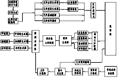
The invention provides a method for integrally automatically generating pipeline designs. The method includes steps of coding all commonly used pipeline elements by the aid of computers, forming foundation elements corresponding to codes and storing the foundation elements in databases; determining positions of starting points and ending points of pipelines and initial connected equipment and final connected equipment of the pipelines; collecting all elements connected with the pipelines and determining connection logical relations among the elements; determining the codes of the pipeline elements, retrieving the foundation elements of the corresponding elements from the databases according to the codes of the elements; retrieving data of the foundation elements of the first elements to form three-dimensional graphs and positioning the three-dimensional graphs at the starting points of the pipelines; computing coordinates of the positions of outlets of the first elements according to coordinates of the positions of the starting points of the pipelines and information of the data of the foundation elements of the first elements, utilizing the coordinates of the outlets as starting points of the second elements and connecting the second elements with the first elements according to set logical relations; sequentially retrieving all the elements in the pipelines from the databases, connecting the elements with one another according to coordinate positioning modes and the logical relations and forming three-dimensional models of the pipelines. The method has the advantages that the design efficiency can be greatly improved, an error rate can be reduced, and the design quality can be enhanced.
Description
technical field [0001] The invention relates to the technical field of pipeline design, in particular to an integrated automatic generation method for pipeline design. Background technique [0002] The integrated design of pipeline components is one of the most core designs in the design work of power plants. The conventional method is to use the CAD graphic design environment to generate a series of plane diagrams to represent the three-dimensional orientation of pipelines and components with multi-directional and multi-angle projection relationships. According to the design conditions, by manually repeatedly searching the different contents in the typical pipeline design manual, find out the various design parameter attributes of each component, combine graphic statistics and calculations, and generate a material report, and achieve the design through the combination of the above-mentioned plan and material report Intent to complete the power plant construction drawing des...
Claims
Application Information
Patent Timeline
Application Date:The date an application was filed.
Publication Date:The date a patent or application was officially published.
First Publication Date:The earliest publication date of a patent with the same application number.
Issue Date:Publication date of the patent grant document.
PCT Entry Date:The Entry date of PCT National Phase.
Estimated Expiry Date:The statutory expiry date of a patent right according to the Patent Law, and it is the longest term of protection that the patent right can achieve without the termination of the patent right due to other reasons(Term extension factor has been taken into account ).
Invalid Date:Actual expiry date is based on effective date or publication date of legal transaction data of invalid patent.

