Fan

An electric fan and space technology, applied in the field of electric fans, can solve problems such as low output, and achieve the effects of increasing discharge flow, speed and strength, and improving production efficiency.

Inactive Publication Date: 2015-01-28
河成又
View PDF8 Cites 2 Cited by
  • Summary
  • Abstract
  • Description
  • Claims
  • Application Information

AI Technical Summary

Problems solved by technology

Relatively low output per unit of input energy used by the motor

Method used


Image

  • Fan
  • Fan
  • Fan

Examples


Embodiment Construction

[0037] Hereinafter, preferred embodiments of the present invention will be described in detail with reference to the accompanying drawings.

[0038] Reference numerals are now understood with reference to the drawings, in which the same reference numerals are used in different drawings to designate the same or similar parts. If, in the specification, a detailed description of a known function or construction would unnecessarily obscure the gist of the present invention, the detailed description will be omitted.

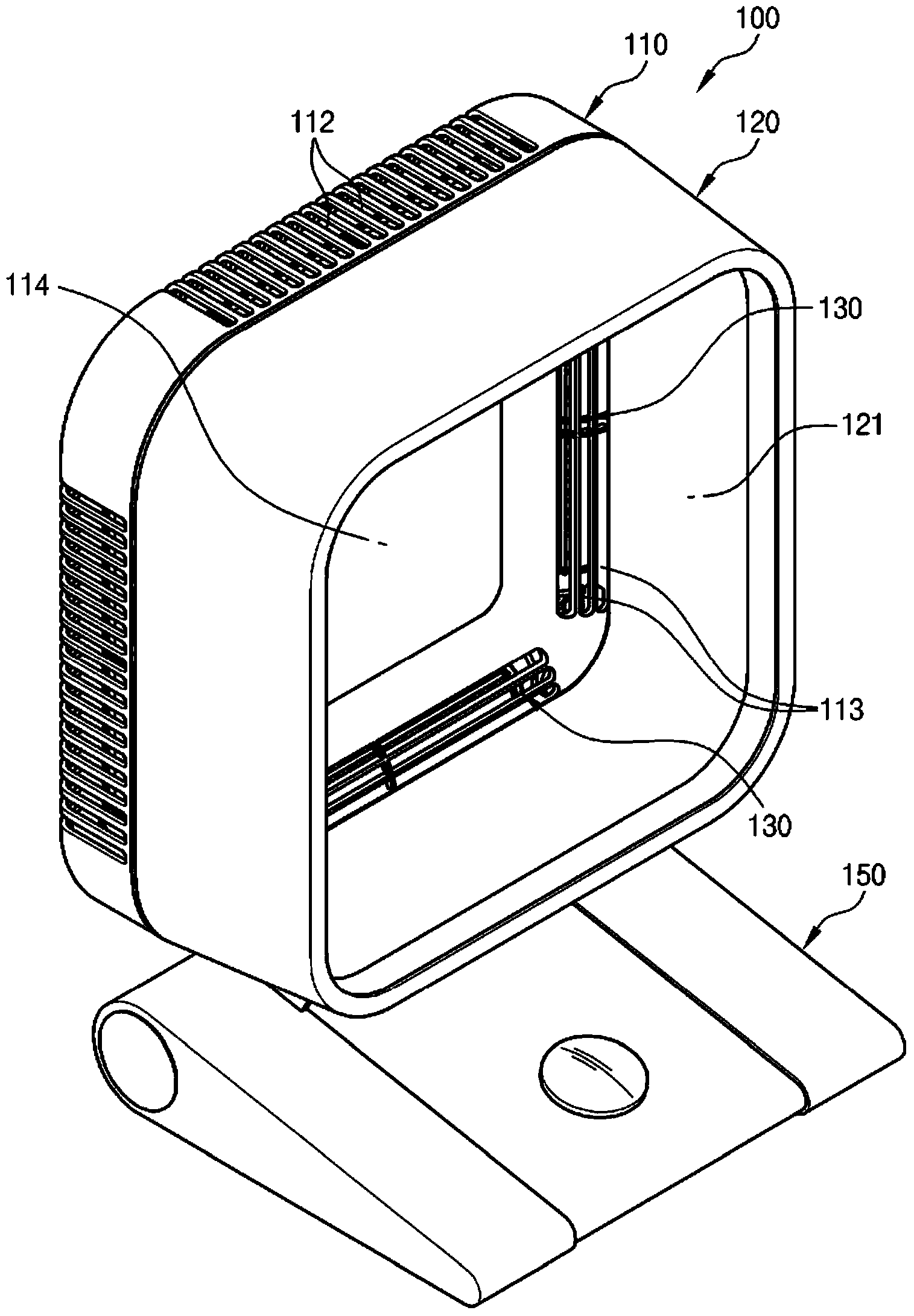
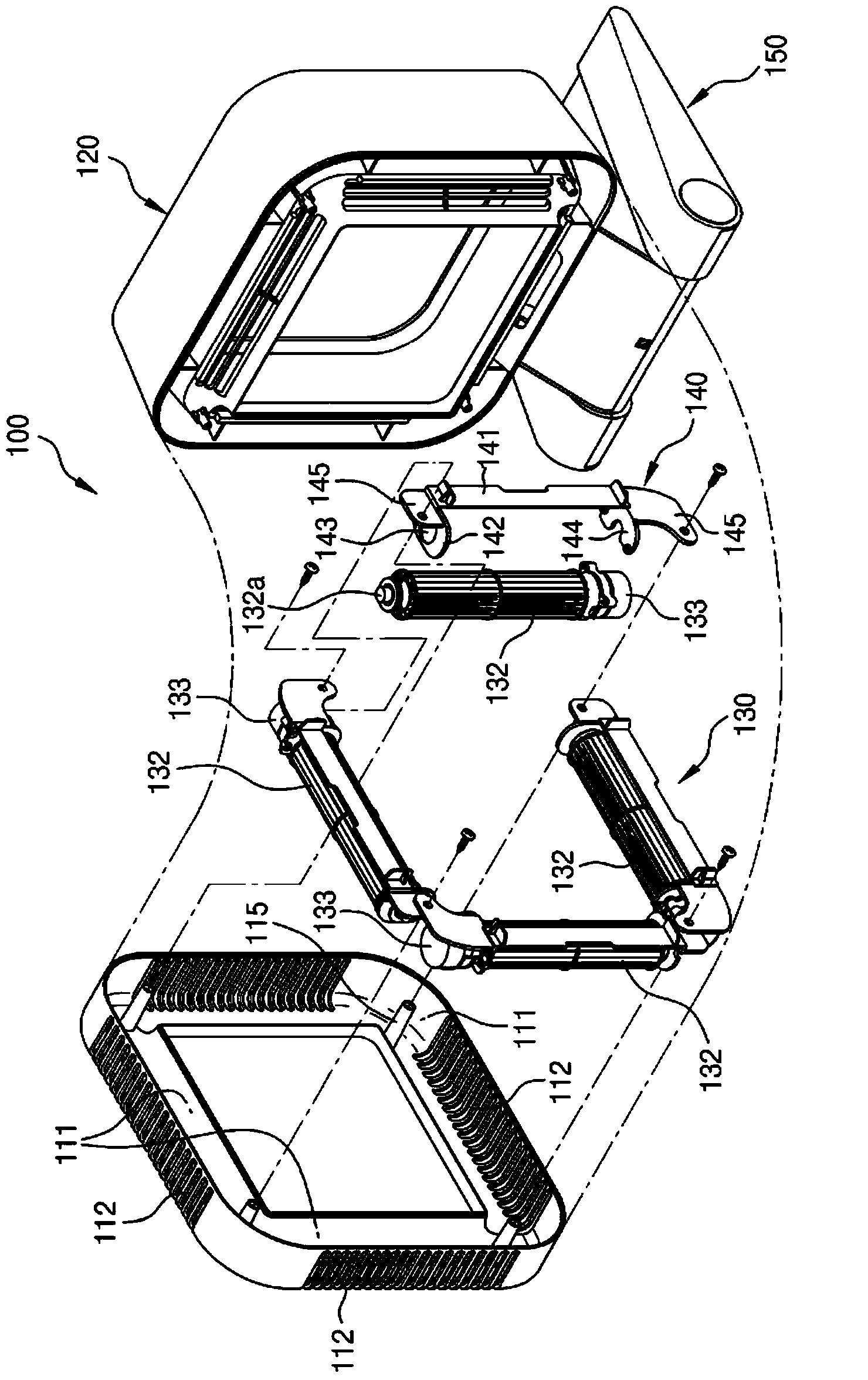
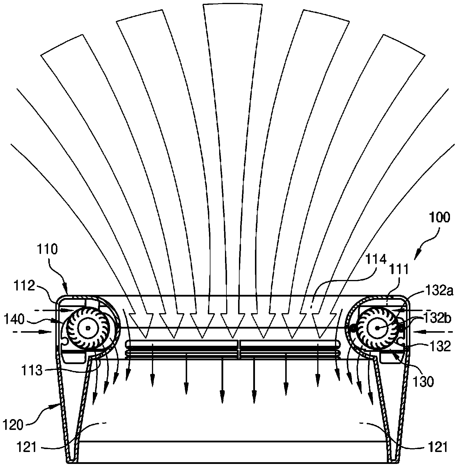
[0039] figure 1 is a perspective view showing the electric fan according to the present invention. figure 2 is an exploded perspective view showing the electric fan according to the present invention. image 3 is a sectional view showing the electric fan according to the present invention. Figure 4 is a perspective view showing an electric fan according to another embodiment of the present invention. Figure 5 is a sectional view showing an electric fan accordin...


PUM


Abstract

A fan of the present invention comprises: a case as a frame having an internal space, a first opening formed in the middle thereof, and inlet and outlet holes formed in the inner and outer surfaces of the periphery of the frame; a rotational part with blades mounted in the internal space, the blades being rotated by a power means to draw external air through the inlet holes into the internal space and to discharge it through the outlet holes; and a cover mounted on the front of the case and provided with a second opening communicating with the first opening so as to discharge the air from the inside of the second opening through the outlet holes towards the outside

Description

technical field [0001] The present invention relates generally to an electric fan, and more particularly to an electric fan constructed in such a manner that the impellers are arranged on corresponding peripheral parts of a housing constructed to have a plurality of The polygonal shape of the segments enables to increase the air discharge flow per unit of air flow, thereby increasing the wind intensity. Background technique [0002] Generally, a household electric fan includes a set of blades or fins arranged on a shaft and rotating about the shaft, and a drive unit that rotates the blades to generate air flow. The movement and circulation of the air creates a breeze that cools the user as heat is carried away from the user's skin by convection and evaporation. [0003] Such electric fans can be constructed in a variety of different sizes and shapes. For example, it may be a ceiling fan with a diameter of 1 m or more. Typically, such ceiling fans are suspended from the ce...

Claims


Application Information

Patent Timeline
Patent Type & Authority Applications(China)
IPC IPC(8): F04D25/08F04D29/40
CPCF04D25/08F04F5/16F04D17/04F04D25/166F04D29/40F04D19/002F04D25/06F04D29/522
Inventor 河成又
Owner 河成又
Why Eureka
Try Eureka