
Special receiving apparatus for ball valve blanking and discharging kneader

A technology of material receiving device and kneader, which is applied in the direction of mixer, mixer accessories, dissolving, etc., can solve the problems of inconvenient discharge of materials, inconvenient removal of material receiving box, and influence on production efficiency, so as to reduce labor intensity and facilitate daily life Maintenance and overhaul, involving reasonable effects

Inactive Publication Date: 2015-02-04
NANTONG KNEADING MIXING MACHINE
View PDF6 Cites 0 Cited by
  • Summary
  • Abstract
  • Description
  • Claims
  • Application Information

AI Technical Summary

Problems solved by technology

[0003] For a larger kneader, it is inconvenient to discharge the material from it. The traditional method is to first place a receiving box under the kneading kettle, and then turn the kneading kettle as a whole so that the upper end opens downward to pour out the material.
Due to the large mass of the kneading kettle, it is quite inconvenient to rotate, and the material will splash out if you are not careful, and it is also inconvenient to remove the receiving box from the bottom of the kneading kettle, which seriously affects the production efficiency

Method used


Image

  • Special receiving apparatus for ball valve blanking and discharging kneader

Examples


Embodiment 1

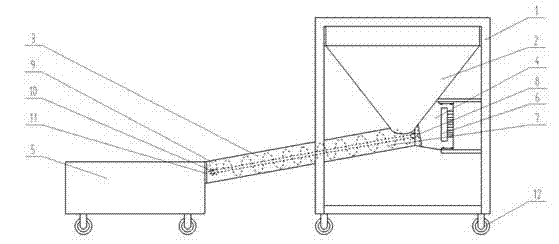
[0017] In order to realize the design original intention of the present invention, the feeding device 4 includes a driving motor 6 and a screw 7 . The drive motor 6 is arranged on the outer surface of the corresponding side of the connection position of the feed pipe 3 on the material receiving box 2, and the drive motor 6 drives the screw rod 7 to work. One end of the screw rod 7 is connected with the drive shaft 8 of the drive motor 6, and the other end is connected with the drive shaft 8 of the drive motor 6. The fixed frame 9 that is arranged on the delivery pipe 3 is connected. The fixed frame 9 is fixedly connected to the top position of the inner surface of one end of the feeding pipe 3, and the middle position of the fixed frame 9 is provided with a bearing 10, and the middle of the bearing 10 is provided for the screw rod 7 to pass through. The material is conveyed to the receiving box 2 by means of the screw 7, and the position of the screw 7 is fixed to reduce the o...

Embodiment 2

[0019] On the basis of embodiment 1, the feeding device 4 and the feed pipe 3 are kept inclined as a whole, and the end of the feed pipe 3 connected to the receiving box 2 is higher than the end of the feed pipe 3 connected to the material collection box 5; the inclination angle is 5 -20°, which is convenient for the accumulation of materials in the receiving box 2 and the rapid discharge of materials.

Embodiment 3

[0021] On the basis of Embodiment 1 or 2, a filter screen 11 is provided at the connection between the feeding pipe 3 and the material collection box 5, which can prevent the viscous material from being mixed with large and fast granular substances.


PUM


Abstract

The invention discloses a special receiving apparatus for a ball valve blanking and discharging kneader. The apparatus comprises a support frame, a receiving box, a conveying tube, conveying devices and a material collecting box. The top of the support frame is in welded connection with the top of the funnel-shaped receiving box, and the cylindrical conveying tube is arranged between the receiving box and the material collecting box. One end of the conveying tube is in welded connection with the bottom of the receiving box, the other end of the conveying tube is in welded connection with the upper portion of any side surface of the material collecting box, and the conveying devices are arranged in the conveying tube and on the receiving box. The apparatus solves the problem of manual material receiving inconvenience of the ball valve blanking and discharging kneader and reduces the labor intensity of workers, the design of a certain angle is beneficial to the material collection, and the arrangement of pulleys at the bottom of the support frame and the bottom of the material collecting box is convenient for the daily maintenance and unkeeping of the apparatus.

Description

technical field [0001] The invention relates to an auxiliary device of a kneader, in particular to a special material receiving device for a kneader with discharge under a ball valve. Background technique [0002] The kneader is an ideal equipment for kneading, mixing, vulcanization and polymerization of high-viscosity and elastic-plastic materials. The kneader can be used to produce silicone rubber, sealant, hot melt adhesive, food rubber base, pharmaceutical preparations, etc. The kneader is a special mixing and stirring device with two Σ paddles. The fast paddle usually rotates at 42 rpm, and the slow paddle usually rotates at 28 rpm. Different paddle speeds make the kneaded materials quickly Mix well. [0003] For a larger kneader, it is inconvenient to discharge the material from it. The traditional way is to first place a receiving box under the kneading kettle, and then turn the kneading kettle as a whole so that the upper opening opens downward to pour out the mate...

Claims


Application Information

Patent Timeline
Patent Type & Authority Applications(China)
IPC IPC(8): B01F15/02
Inventor 王均炎
Owner NANTONG KNEADING MIXING MACHINE
Learn More