

A swinging folded plate photocatalytic reaction device
A photocatalytic reaction and plate-type technology, which is applied in chemical/physical processes, chemical instruments and methods, etc., to achieve the effects of improving light energy utilization, increasing contact area, and increasing illuminated area
Inactive Publication Date: 2016-04-20
INNER MONGOLIA NORMAL UNIVERSITY
View PDF4 Cites 0 Cited by
- Summary
- Abstract
- Description
- Claims
- Application Information
AI Technical Summary
Problems solved by technology
It has not been reported that the interface of the catalyst can be renewed to improve the reaction rate and light energy utilization, so that the catalyst, reactant and light energy can be fully contacted to achieve continuous reaction.
Method used
View moreImage
Smart ImageViewing Examples

Examples
Embodiment Construction
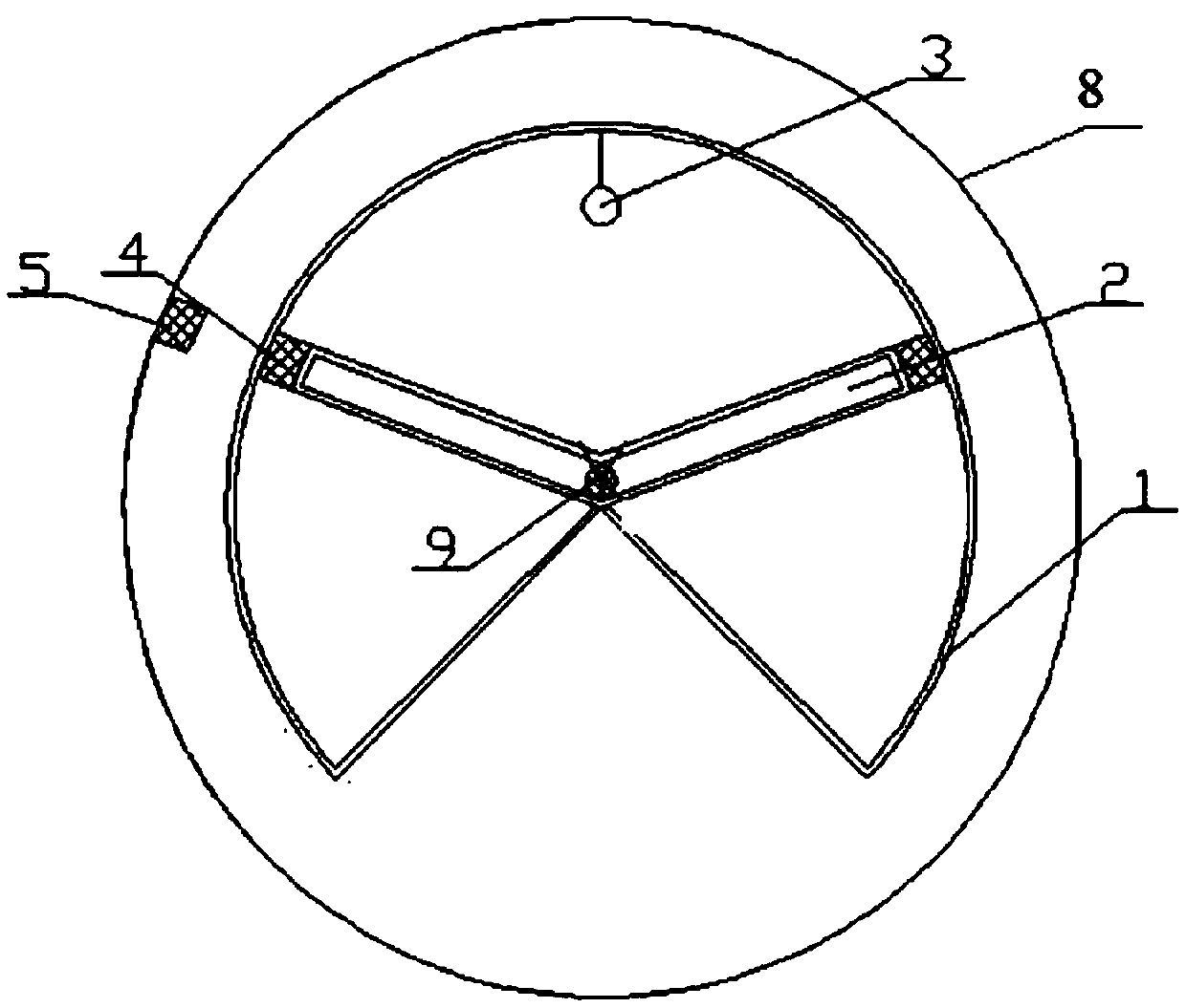
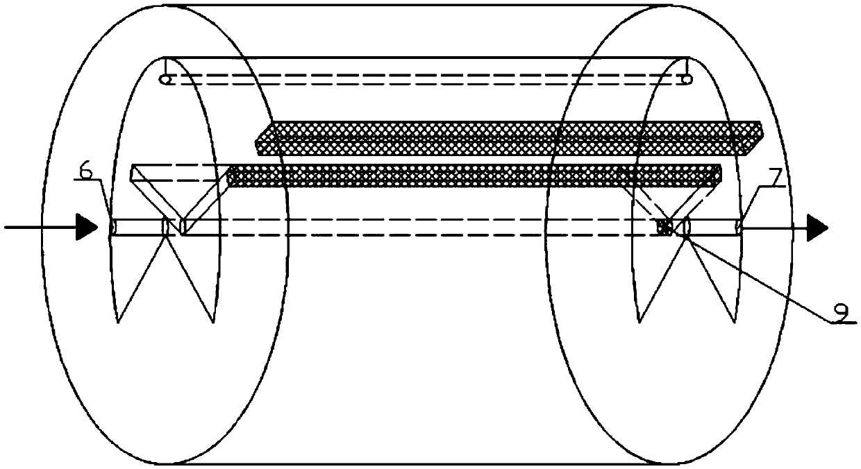
[0022] Such as Figure 1-3 As shown, the device is implemented in the following steps,
[0023] 1) Open the air inlet 6 to fill the catalyst.
[0024] 2) Turn on the motor, and the permanent magnet 5 drives the folded plate 2 to swing.
[0025] 3). Pass the reactant gas from the air inlet 6 and open the air outlet 7 to keep the gas circulating.
[0026] 4) Turn on the light source 3, and the catalyst fully reacts with the reaction gas.
[0027] 5). After the reaction is completed, a certain amount of inert gas is introduced and after the reaction gas has all flowed out from the gas outlet 7, the motor and the light source 3 are turned off.
[0028] 6) Open the air inlet 6 and take out the used catalyst.
Login to View More PUM
 Abstract
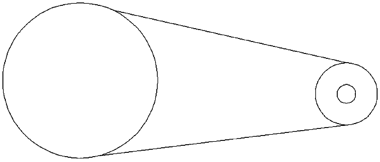
The invention discloses a swinging folded plate type photo-catalytic reaction device. The device comprises an outer cylinder barrel, a folded plate, a light source, arc-shaped permanent magnets, permanent magnets, a ceramic filter and an outer device barrel, wherein the folded plate comprises two symmetric reaction chambers, a gas inlet and a gas outlet; the gas inlet also serves as an inlet and an outlet for adding a catalyst; the folded plate is mounted in the center of the outer cylinder barrel; the light source is mounted on the outer cylinder barrel; the arc-shaped permanent magnets are mounted and fixed at two ends of the folded plate; the permanent magnets are fixed on the outer device barrel corresponding to the arc-shaped permanent magnets at the two ends of the folded plate; the outer device barrel is driven by a motor through a belt, so that the permanent magnets are driven to rotate, the arc-shaped permanent magnets and the folded plate are driven to rotate together, the permanent magnets and the arc-shaped permanent magnets are magnetically attracted to each other, and the outer cylinder barrel does not rotate along with the folded plate. The device is driven by the motor, so that the folded plate can swing, the catalyst can be stirred, the problems of vibration and accurate positioning in mechanical stirring are solved, and the contact area between the catalyst and the light source can be increased.
Description
Technical field [0001] The invention relates to a photocatalytic experimental reaction device, belonging to the field of photocatalytic instrument devices. Background technique [0002] Photocatalysis technology is a new technology developed in the 1970s. Photocatalysis is based on a photocatalyst that promotes the catalytic redox reaction of reactants under light conditions. There is a forbidden band (Forbidden Band, BandGap) between the Valence Band (VB) and the Conduction Band (CB) of the semiconductor photocatalyst. When the photon energy is higher than the semiconductor band gap, the valence band electrons of the catalyst Inter-band transition occurs, from the valence band to the conduction band, resulting in photo-generated electrons (e-) and holes (h+). Photogenerated electrons (e-) have strong reducibility, such as: it can make oxygen trapped on the surface of the catalyst to form superoxide anion O 2 2- , Oxygen molecular ion O 2 - ; And light-generated holes have stron...
Claims
Login to View More Application Information
Patent Timeline
 Patent Type & AuthorityPatents(China)
IPC IPC(8): B01J8/08
CPCB01J8/08B01J2208/0084
Inventor徐爱菊王奖贾美林特格希包永胜照日格图
OwnerINNER MONGOLIA NORMAL UNIVERSITY