Balloon catheter fluid automatic clearing system

一种清除系统、流体的技术,应用在导管系统领域,能够解决压力传感器宽误差范围、球囊壁破裂、损伤等问题,达到优化体积、早发现和响应的效果

Active Publication Date: 2015-02-04
CRYOFOCUS MEDTECH (SHANGHAI) CO LTD
View PDF8 Cites 8 Cited by
  • Summary
  • Abstract
  • Description
  • Claims
  • Application Information

AI Technical Summary

Problems solved by technology

Second, the pressure sensor will have a wide margin of error at its set point
Because too much pressure can rupture the balloon wall, pushing the torn material outward and further stretching the surrounding tube wall, causing injury

Method used


Image

  • Balloon catheter fluid automatic clearing system
  • Balloon catheter fluid automatic clearing system
  • Balloon catheter fluid automatic clearing system

Examples


Embodiment Construction

[0030] The following describes in detail the presently most preferred modes of carrying out the invention. The description is not intended to limit the present invention, but is only used to illustrate the basic principles of the specific embodiments of the present invention. The protection scope of the present invention is defined by the appended claims.

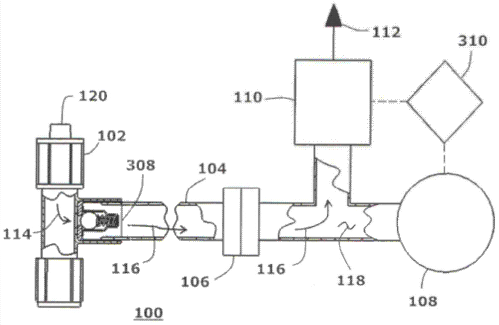
[0031] Such as figure 1As shown, the present invention provides a fluid removal system 100 capable of receiving fluid 114 from an inlet 120 of a pressure relief valve 102 . The pressure relief valve 102 is a standard spring actuated pressure relief valve with a preset burst pressure differential in the range of 20 psig to 750 psig. Pressure relief valve 102 functions like a check valve, allowing flow in one direction and blocking flow in the opposite direction. Fluid can pass through the relief valve 102 only when the internal fluid pressure rises above the burst pressure of the relief valve 102 . For the present invent...


PUM


Abstract

The invention relates to a balloon catheter fluid automatic clearing system comprising a spring-driven decompression valve, the decompression valve is provided with an inlet opening and an outlet opening, wherein the inlet opening is connected to a fluid cavity and used for receiving an inflowing fluid, the outlet opening is used for discharging the inflowing fluid, the outlet opening is connected to a pressure cavity through the fluid, the fluid clearing system also comprises an electromechanical pressure switch and an electric control electromagnetic valve which can be used as a pressure release valve, and the pressure switch and the electromagnetic valve are communicated with the pressure cavity fluid.

Description

technical field [0001] The present invention relates to a catheter system, in particular, to a balloon catheter fluid automatic removal system. Background technique [0002] A typical industrial fluid removal system usually uses a pressure sensor (eg, pressure switch, pressure transducer, etc.) to detect the fluid pressure in the pressure chamber, and then releases the high pressure directly from the pressure chamber through a discharge valve. This typical industrial fluid removal system does not place a relief valve in front of the pressure sensor, thus making it easy to implement. However, this arrangement is not suitable for medical device applications. Specifically, the layout of these two components is critical. If these two components (pressure sensor and bleed valve) are installed in a system architecture, a very long fluid connection line is required. This increases the volume of the balloon lumen, making it more difficult to evacuate trapped air. Before inflatin...

Claims


Application Information

Patent Timeline
Patent Type & Authority Applications(China)
IPC IPC(8): B08B9/032
CPCA61M25/10186A61B2018/0022A61B2018/0212A61B2018/0262A61B18/02Y10T137/7761A61M60/274
Inventor 泰克·布·杨敏·弗兰克·曾
Owner CRYOFOCUS MEDTECH (SHANGHAI) CO LTD
Why Eureka
Try Eureka