A method for boring a rotary hinge water seal seat using a rotary hinge water seal seat boring device

A water seal seat and boring technology, which is applied in the field of boring, can solve the problems of excessive coaxiality of the reaming shaft hole, inability to guarantee the accuracy, and the rigidity of the boring bar cannot meet the requirements for use, so as to ensure the processing accuracy and quality requirements. , Simple structure, easy to use effect

Active Publication Date: 2017-05-17
SINOHYDRO BUREAU 12 CO LTD
View PDF16 Cites 1 Cited by
  • Summary
  • Abstract
  • Description
  • Claims
  • Application Information

AI Technical Summary

Problems solved by technology

[0007] The first method is boring first and then welding, which has high requirements on the control of welding deformation. Often, poor control of welding deformation will cause the coaxiality of the hinge shaft hole to be out of tolerance, which will affect the flexibility of the hinge shaft rotation.
Although the second method does not have the influence of welding deformation, it is possible to bore the hinge shaft with a short length, but in the case of a long workpiece and a small diameter of the shaft hole, the rigidity of the boring bar will not meet the requirements for use, and it is still impossible Direct boring with a boring machine
[0013] The above technical solution solves the problem that the long-axis butt joint flange connection reaming hole cannot be processed and the accuracy cannot be guaranteed
[0014] In the existing technical solutions, there is no boring device and a method for using the device to process the shaft hole of the hinge plate after the integral welding of the rotary hinge water seal is not yet available.

Method used


Image

  • A method for boring a rotary hinge water seal seat using a rotary hinge water seal seat boring device
  • A method for boring a rotary hinge water seal seat using a rotary hinge water seal seat boring device
  • A method for boring a rotary hinge water seal seat using a rotary hinge water seal seat boring device

Examples


Embodiment 1

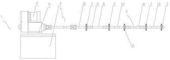
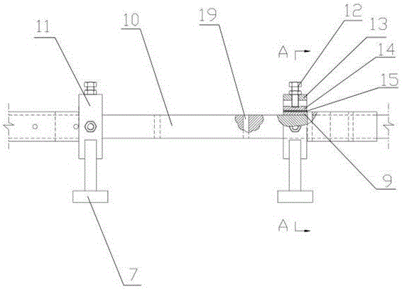
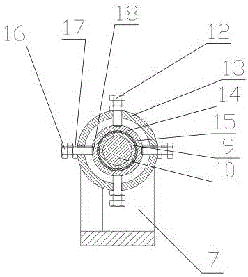
[0045] exist figure 1 In the described embodiment, a boring device for a rotary hinge water seal seat includes a power system 1, a force transmission system 2 and a boring system 3, and the force transmission system 2 is a set of transmission universal couplings. The power system 1 includes a sliding table seat 4, a sliding table 5 and a boring head 6. The boring head 6 is connected with the sliding table 5 and slides along the sliding table seat 4. The boring head 6 is connected with the force transmission system 2, and the force transmission system 2 is connected with the The boring system 3 is connected. The boring system 3 includes a plurality of support seats 7, connecting rods 8, connecting sleeves 9 and boring bars 10. The boring bars 10 are arranged in sections, and each group of hinge shaft holes is correspondingly provided with a section of boring bars 10. , the boring tool hole 19 is set on the boring bar 10 (see figure 2 ). The support seat 7 is provided with a ...


PUM


Abstract

The invention discloses a rotating hinge water seal seat boring device. The rotating hinge water seal seat boring device comprises a power system, a force transfer system and a boring system; the power system comprises a sliding table seat, a sliding table and a boring head, wherein the boring head is connected with the sliding table and slides along the sliding table seat, the boring head is connected with the force transfer system, and the force transfer system is connected with the boring system; the boring system comprises a plurality of support seats, connecting rods, a connecting sleeve and a boring rod, wherein a radial adjusting mechanism is arranged on each support seat, the boring rod corresponds to an axial hole to be bored, and the two ends of the boring rod are respectively, coaxially and rotatably connected with the radial adjusting mechanism on each support seat; every two adjacent support seats are respectively and rotatably connected through the connecting rod. The invention also discloses a method for boring a rotating hinge water seal seat by using the boring device. The boring device and the boring method are simple in structure and convenient to use, the coaxiality of each hinge axle hole of the rotating hinge water seal seat is ensured by means of the coaxiality of the support seats, and the machining precision requirement can be met.

Description

technical field [0001] The invention relates to the technical field of boring, in particular to a method for boring a rotary hinge water seal seat using a rotary hinge water seal seat boring device. Background technique [0002] The gate is an active water retaining structure in a hydraulic structure. It is used to close, open or partially open the water orifice to control the water level, regulate the flow, pass the ship, discharge the sediment, etc. [0003] Arc gate is a very common type of hydraulic metal structure gate. The center of the hinge shaft is arranged at the center of the arc-shaped panel. When opening the door, it is only necessary to overcome the resistance moment of the gate's own weight and the frictional resistance of the water seal and the hinge shaft to the shaft center. Therefore, it has the advantages of labor-saving opening and closing, reliable operation, and good discharge conditions. Etc. Usually, arc gates are selected as working gates in spill...

Claims


Application Information

Patent Timeline
Patent Type & Authority Patents(China)
IPC IPC(8): B23B41/00B23B35/00
CPCB23B35/00B23B41/00
Inventor 易拥林毛新富
Owner SINOHYDRO BUREAU 12 CO LTD
Why Eureka
Try Eureka