Stroke control device of grinding machine working table

A stroke control and worktable technology, which is applied to grinding drive devices, grinding machine parts, manufacturing tools, etc., can solve the problem that the real-time position cannot be fed back to the machine tool control system, etc. Effect

Inactive Publication Date: 2015-02-04
柳州金盛重型数控机床有限责任公司
View PDF6 Cites 1 Cited by
  • Summary
  • Abstract
  • Description
  • Claims
  • Application Information

AI Technical Summary

Problems solved by technology

[0003] The purpose of the present invention is to provide a grinder table stroke control device, which can solve the problem that the real-time position of the grinder table driven by the hydraulic cylinder cannot be fed back to the machine tool control system during the movement process

Method used


Image

  • Stroke control device of grinding machine working table
  • Stroke control device of grinding machine working table

Examples


Embodiment Construction

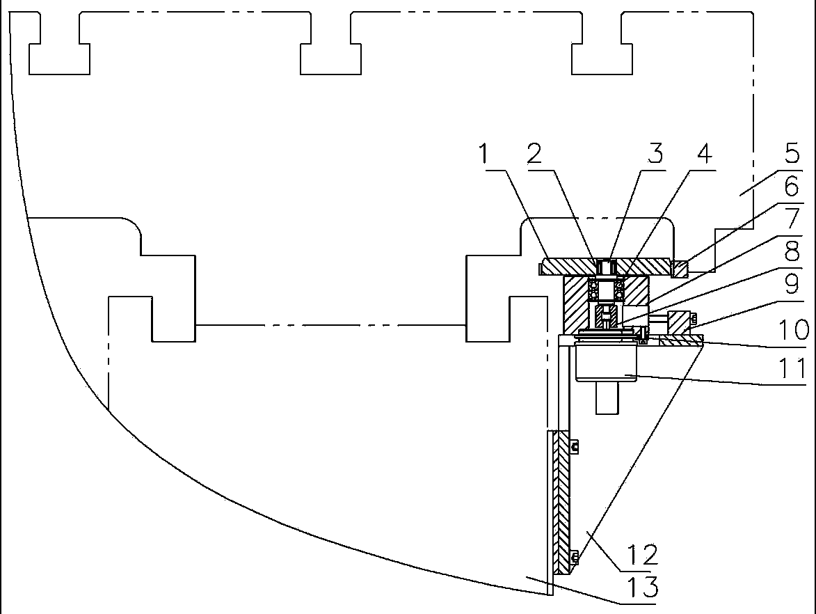
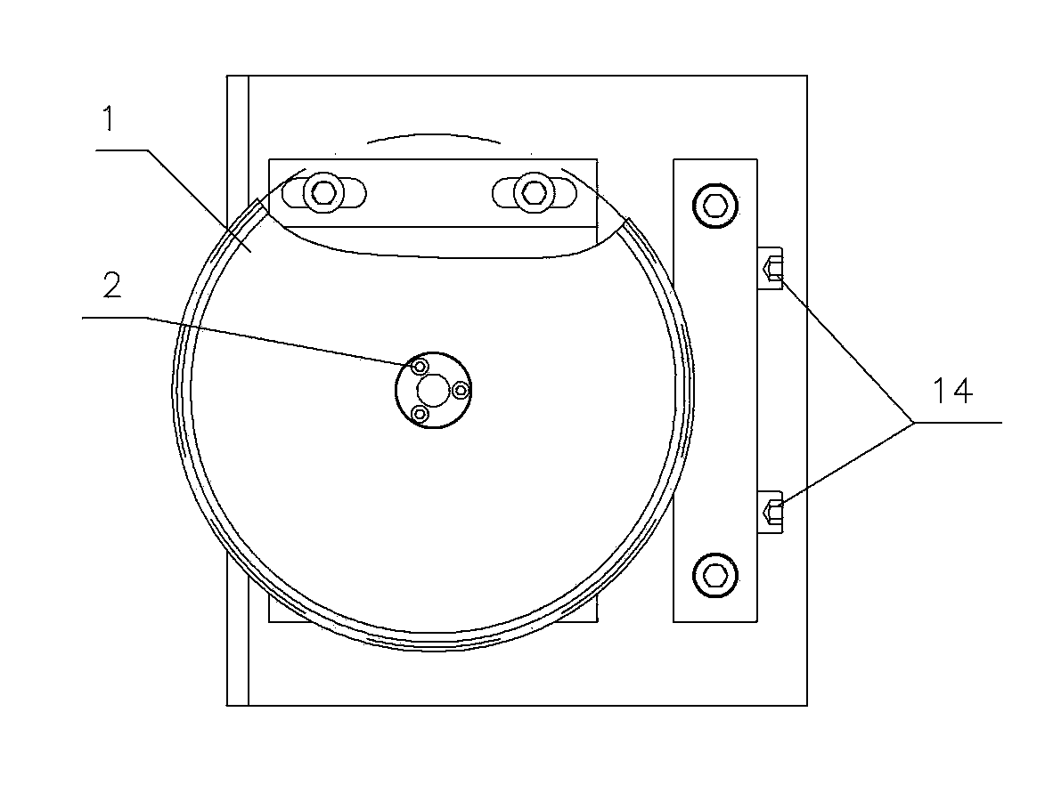
[0012] The present invention will be described in further detail below in conjunction with accompanying drawing embodiment:

[0013] figure 1 with figure 2 The stroke control device of the grinder workbench shown mainly includes the machine tool control system, the mobile worktable 5, the rack 6, the gear 1 and the rotary encoder 11. The mobile workbench 5 is installed on the machine bed 13 and is driven by a hydraulic cylinder. A rotary encoder 11 electrically connected to the machine tool control system is installed on the bed 13. The machine tool control system in this embodiment is a PLC controller. The rotating shaft of the rotary encoder 11 is connected with the gear 1 through the rotary shaft 3, and the gear 1 is fixedly installed The rack 6 on the mobile worktable 5 is meshed and connected, and the rack 6 is set along the linear motion direction of the mobile workbench 5 and moves with the mobile worktable 5; the gear 1 meshing with the rack 6 is fixed on the machine...


PUM


Abstract

The invention discloses a stroke control device of a grinding machine working table, and relates to the technical field of manufacturing of mechanical equipment. The stroke control device comprises a machine tool control system and the movable working table driven by a hydraulic cylinder; the movable working table is arranged on a machine tool body. The stroke control device is characterized in that a rotary encoder electrically connected with the machine tool control system is arranged on the machine tool body; a rotary shaft of the rotary encoder is connected with a gear; the gear is in meshing connection with a rack arranged on the movable working table; the rack is arranged in the straight-line motion direction of the movable working table. Compared with the prior art, the gear and the rack transmit to drive the encoder to rotate, and the straight-line motion process of the grinding machine working table is fed back to the machine tool control system in real time through the coaxial rotary encoder; therefore, the machining precision is improved, and grinding machining of a concave-convex curve on the surface of a part and automatic distance-fixed reversing of the working table can be achieved; a machine tool is easy, convenient and rapid to operate.

Description

technical field [0001] The invention relates to the technical field of mechanical equipment manufacturing, in particular to a stroke control device applied to a grinder workbench. Background technique [0002] Grinding machine is a device that grinds the surface of the workpiece by using abrasive tools. Most of the reciprocating motion of the grinding machine table is driven by hydraulic cylinders, and the fixed-distance reversing action of the table is completed by manually adjusting the travel switch. This control method only plays the role of simple fixed-distance reversing, and the real-time position during the movement of the table cannot be fed back to the machine tool control system, so that the function of the grinding machine is limited, and it is impossible to realize such as concave-convex curve grinding, automatic fixed-distance reversing and other functions. Contents of the invention [0003] The object of the present invention is to provide a grinder table s...

Claims


Application Information

Patent Timeline
Patent Type & Authority Applications(China)
IPC IPC(8): B24B47/06B24B47/22
CPCB24B47/22B24B47/06
Inventor 邹雪巍
Owner 柳州金盛重型数控机床有限责任公司
Why Eureka
Try Eureka